Previous: Turbulence Up: TCFD – GUI Setup Next: Boundary condition: Outlet
This is an automatically generated documentation by LaTeX2HTML utility. In case of any issue, please, contact us at info@cfdsupport.com.
Boundary condition: Inlet
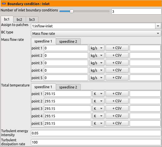
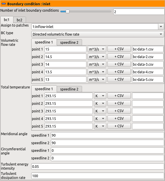
Examples of inlet boundary conditions settings are displayed in Figures ![Node44 7 [*]](https://www.cfdsupport.com/wp-content/uploads/2022/02/crossref.png) and
and ![Node44 7 [*]](https://www.cfdsupport.com/wp-content/uploads/2022/02/crossref.png) .
It is possible to define an arbitrary number of inlet boundary conditions. They can be assigned to individual inlet patches defined in the section “Components”.
There are several possible ways how to prescribe the desired behavior of the simulated fields at the inlet to the computational domain: Prescribing a fixed inflow (either in kg/s or m
.
It is possible to define an arbitrary number of inlet boundary conditions. They can be assigned to individual inlet patches defined in the section “Components”.
There are several possible ways how to prescribe the desired behavior of the simulated fields at the inlet to the computational domain: Prescribing a fixed inflow (either in kg/s or m /s), or requesting a fixed total pressure. The choice of the boundary conditions is done by selection of one item of the drop-down list “Inlet BC”. The rest of the panel is then adjusted to the user’s choice.
Parameters of the turbulence model chosen in the section “Turbulence” are common to all boundary condition types. If
  or
or  model is used, then the parameters “Turbulent energy intensity” and “Turbulent dissipation” are available. If Spalart-Allmaras model is used, then “Turbulent eddy viscosity” is available.
![Node44 7 [*]](https://www.cfdsupport.com/wp-content/uploads/2022/02/crossref.png) and
and ![Node44 7 [*]](https://www.cfdsupport.com/wp-content/uploads/2022/02/crossref.png) .
It is possible to define an arbitrary number of inlet boundary conditions. They can be assigned to individual inlet patches defined in the section “Components”.
There are several possible ways how to prescribe the desired behavior of the simulated fields at the inlet to the computational domain: Prescribing a fixed inflow (either in kg/s or m
.
It is possible to define an arbitrary number of inlet boundary conditions. They can be assigned to individual inlet patches defined in the section “Components”.
There are several possible ways how to prescribe the desired behavior of the simulated fields at the inlet to the computational domain: Prescribing a fixed inflow (either in kg/s or m- “Turbulent energy intensity” sets the fraction of the inlet turbulent and total kinetic energy
 , typically five per cent (0.05).
 - “Turbulent dissipation” sets the inlet turbulent energy dissipation
 within the
  models, or the inlet turbulent energy dissipation rate
  within the
  turbulent model.
 - “Turbulent eddy viscosity” sets the incoming value of the quantity
 .
.
- “Total pressure”, which is the inlet total pressure
 and
and - “Total temperature”, which is the inlet total temperature
 (only needed and available for compressible simulations).

Figure: Plugin TCFDSource – inlet boundary conditions: Mass flow rate.

Figure: Plugin TCFDSource – inlet boundary conditions: Directed volumetric flow rate.
Previous: Turbulence Up: TCFD – GUI Setup Next: Boundary condition: Outlet


