


- A typical way how to create the mesh of rotating part is to use blockMesh for creating background mesh (a box aligned with the principal axes X,Y,Z), snappyHexMesh for definition and refinement of the mesh boundaries.
- This typical approach ignores the fact that axis of rotation is not aligned with any of the principal axes and it is going to affect the quality of the final mesh (too small cells will be generated) and that dramatically increase computation time (the lower is the cell size the lower could be the highest possible time-step in the simulation).
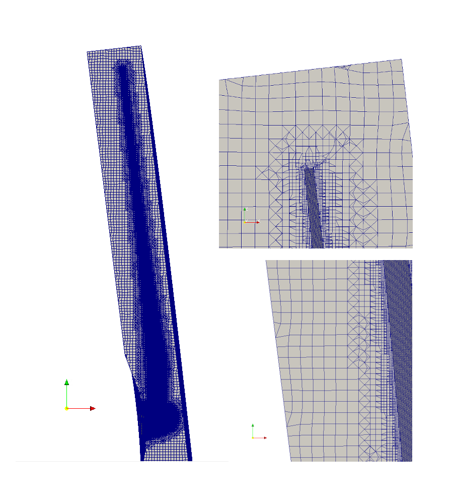
- So therefore the background mesh aligned with the axis of rotation will be generated in order to generate a mesh with highest possible quality – let’s call it aligned mesh in further text – (See figure
 – the comparison of the typical mesh and the aligned mesh).
 - For illustration of this phenomenon one can run the checkMesh utility and compare e.g. the minimum face area of the typical rotating mesh and of the rotating mesh introduced in the following text.
- The minimum face area is
 mm
mm for the typical meshing and respectively
  mm for the mesh.