Previous: Post-processing Up: TCFD – GUI Setup Next: Scripting
This is an automatically generated documentation by LaTeX2HTML utility. In case of any issue, please, contact us at info@cfdsupport.com.
Meshing options: Snappy hex mesh
This panel is visible in advanced mode only. The parts of the default panel are displayed in Figures ![Node49 7 [*]](https://www.cfdsupport.com/wp-content/uploads/2022/02/crossref.png) ,
, ![Node49 7 [*]](https://www.cfdsupport.com/wp-content/uploads/2022/02/crossref.png) ,
, ![Node49 7 [*]](https://www.cfdsupport.com/wp-content/uploads/2022/02/crossref.png) ,
, ![Node49 7 [*]](https://www.cfdsupport.com/wp-content/uploads/2022/02/crossref.png) and
and ![Node49 7 [*]](https://www.cfdsupport.com/wp-content/uploads/2022/02/crossref.png) .
The most important numbers are the refinement levels (minimal and maximal) for individual patches. The mesher will subdivide the cells of the background mesh a few times. The count of these subdivisions is always in the given interval and depends on the vicinity of other patches and the local curvature. The remaining parameters are:
.
The most important numbers are the refinement levels (minimal and maximal) for individual patches. The mesher will subdivide the cells of the background mesh a few times. The count of these subdivisions is always in the given interval and depends on the vicinity of other patches and the local curvature. The remaining parameters are:
![Node49 7 [*]](https://www.cfdsupport.com/wp-content/uploads/2022/02/crossref.png) ,
, ![Node49 7 [*]](https://www.cfdsupport.com/wp-content/uploads/2022/02/crossref.png) ,
, ![Node49 7 [*]](https://www.cfdsupport.com/wp-content/uploads/2022/02/crossref.png) ,
, ![Node49 7 [*]](https://www.cfdsupport.com/wp-content/uploads/2022/02/crossref.png) and
and ![Node49 7 [*]](https://www.cfdsupport.com/wp-content/uploads/2022/02/crossref.png) .
The most important numbers are the refinement levels (minimal and maximal) for individual patches. The mesher will subdivide the cells of the background mesh a few times. The count of these subdivisions is always in the given interval and depends on the vicinity of other patches and the local curvature. The remaining parameters are:
.
The most important numbers are the refinement levels (minimal and maximal) for individual patches. The mesher will subdivide the cells of the background mesh a few times. The count of these subdivisions is always in the given interval and depends on the vicinity of other patches and the local curvature. The remaining parameters are:
- The entry “Feature edges included angle” is a tuning parameter that specifies maximal angle (in degrees) that is considered “sharp” by the mesher. When two faces of a boundary geometry make an angle smaller or equal to this number, then their common edge will be preserved in mesh (the cells’ edges will be aligned with this line), otherwise it may be smoothed away. If zero is given, only open edges of the boundary geometry will be preserved. This parameter is only used by components that are meshed from STL files.
- “Surface hook-up”, which corrects some non-water-proof STL boundaries.
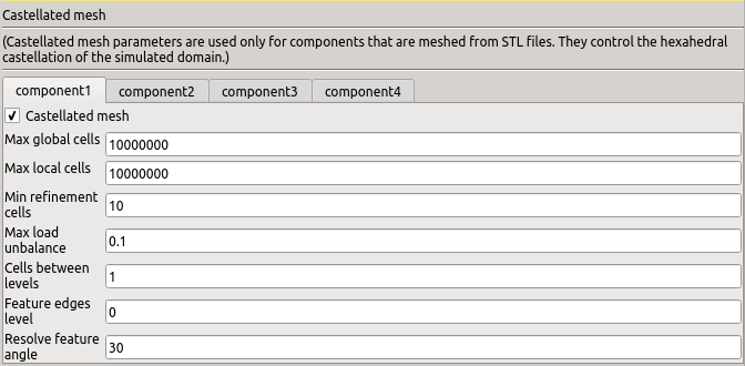
- The switch “Castellated mesh” enables and disables the castellated mesh phase. For normal operation it is always enabled.
- The value “Max global cells” sets a hard limit on the total number of cells to prevent memory overflow.
- The value “Max local cells” sets a soft limit on the number of cells per meshing process. When reached, the redistribution of the cells between the processes is done in a more careful (and slower) way.
- The value “Min refinement” sets a limit on the lowest number of cells refined in previous iteration of the mesher, which still triggers another iteration. If zero is given, the mesh will be refined ideally according to the algorithm of the mesher. Slightly higher values speed up the castellated mesh phase of the meshing without great impact on the quality of the mesh.
- The value “Max load unbalance” is the largest relative difference in number of cells across the mesher’s processes, which is considered low and does not trigger (slow) redistribution.
- The value “Cells between levels” sets the minimal number of consecutive cells of a single refinement level in area where the refinement level dramatically changes.
- The number “Resolve feature angle” is an angle in degrees.

Figure: Plugin TCFDSource – advanced mesh setup: STL manipulation.

Figure: Plugin TCFDSource – advanced mesh setup: Castellated mesh.

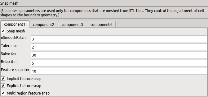
Figure: Plugin TCFDSource – advanced mesh setup: Snap mesh.

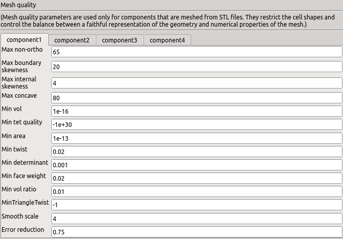
Figure: Plugin TCFDSource – advanced mesh setup: Mesh quality.

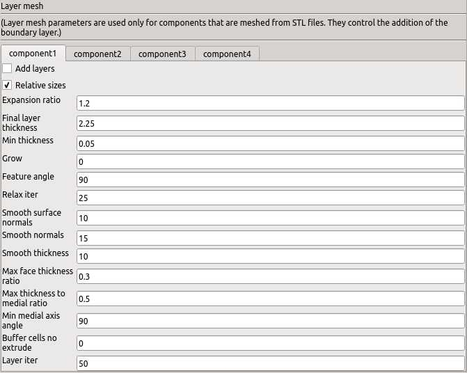
Figure: Plugin TCFDSource – advanced mesh setup: Layer mesh.
Previous: Post-processing Up: TCFD – GUI Setup Next: Scripting


