Previous: snapControls Up: SnappyHexMesh mesh Next: meshQualityControls
This is an automatically generated documentation by LaTeX2HTML utility. In case of any issue, please, contact us at info@cfdsupport.com.
addLayersControls
This block defines parameters for adding boundary layer:
relativeSizes true;
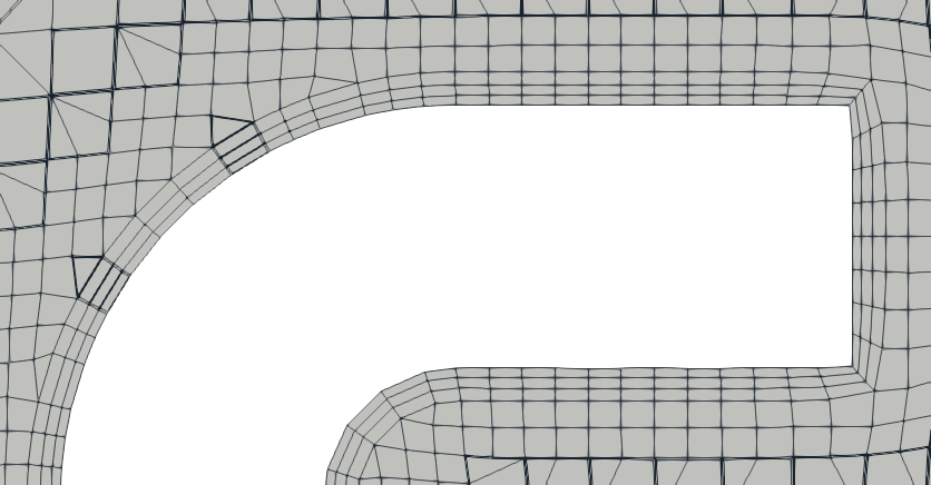
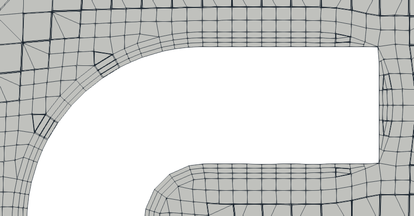
- relativeSizes this parameters enables usage of relative values instead of absolute:
- true – sizes relative to the cell size next to the patch for which adding layers is defined
- false – sizes in absolute values


Figure: relativeSizes: true – false.
layers { C { nSurfaceLayers 3; expansionRatio 1.5; } F { nSurfaceLayers 2; // Wanted thickness of the layer next to the wall. // If relativeSizes this is relative to undistorted size of cell // outside layer.; firstLayerThickness 0.2; } D { nSurfaceLayers 3; thickness 1.0; } }- layers block includes list of patches for which boundary layer is being added
- patch name or regular expression can be used
- the block contains
- nSurfaceLayers – number of layers to be added
- layer parameters (described below)
- Boundary layer is correctly defined by following couple of parameters:
- firstLayerThickness, thickness
- firstLayerThickness, expansionRatio
- finalLayerThickness, expansionRatio
- finalLayerThickness, thickness
- thickness, expansionRatio
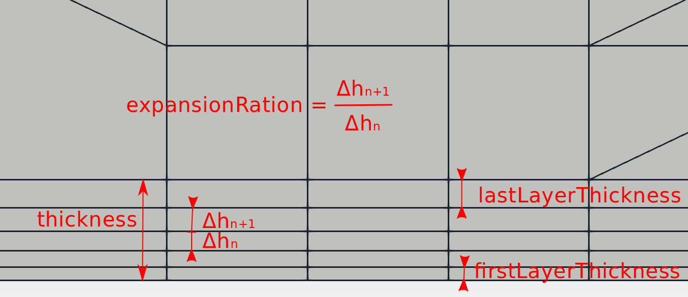
- firstLayerThickness – is the thickness of the first layer in the boundary layer (next to the wall)
- finalLayerThickness – is the thickness of the last layer in the boundary layer
- thickness – is the overall thickness of the whole boundary layer
- expansionRation – expansion ration of neighbouring layers in the boundary layer

Figure: Boundary layer parameters.
expansionRatio 1.2;
finalLayerThickness 0.3;
- Boundary layer parameters for all defined patches (any parameter defined within the layers block prefers to parameters defined here).
minThickness 0.05;
- minThickness – minimum layer thickness below which the layer is not added
nGrow 0;
- nGrow – very experimental – best results with value

featureAngle 150;
- featureAngle – layers are collapsed at the feature edges which see angle above this value, an example of different setups is visualized in Figure
 .
.


Figure: Boundary layer parameters.
- The remaining parameters are very advanced and set to default values. Please read a basic description in the file:
// Stop layer growth on highly warped cells maxFaceThicknessRatio 0.5; // Patch displacement // Number of smoothing iterations of surface normals nSmoothSurfaceNormals 10; // Smooth layer thickness over surface patches nSmoothThickness 10; // Medial axis analysis // Angle used to pick up medial axis points // Note: changed(corrected) w.r.t 17x! 90 degrees corresponds to 130 // in 17x. minMedialAxisAngle 90; // Reduce layer growth where ratio thickness to medial // distance is large maxThicknessToMedialRatio 0.3; // Number of smoothing iterations of interior mesh movement direction nSmoothNormals 15; // Optional: limit the number of steps walking away from the surface. // Default is unlimited. // nMedialAxisIter 10; // Optional: smooth displacement after medial axis determination. // default is 0. // nSmoothDisplacement 90; // (wip)Optional: do not extrude a point if none of the surrounding points is // not extruded. Default is false. // detectExtrusionIsland true; // Mesh shrinking // Optional: at non-patched sides allow mesh to slip if extrusion // direction makes angle larger than slipFeatureAngle. Default is // 0.5*featureAngle. slipFeatureAngle 30; // Maximum number of snapping relaxation iterations. Should stop // before upon reaching a correct mesh. nRelaxIter 25; // Create buffer region for new layer terminations nBufferCellsNoExtrude 0; // Overall max number of layer addition iterations. The mesher will // exit if it reaches this number of iterations; possibly with an // illegal mesh. nLayerIter 10; // Max number of iterations after which relaxed meshQuality controls // get used. Up to nRelaxedIter it uses the settings in // meshQualityControls, // after nRelaxedIter it uses the values in // meshQualityControls::relaxed. nRelaxedIter 25; // Additional reporting: if there are just a few faces where there // are mesh errors (after adding the layers) print their face centres. // This helps in tracking down problematic mesh areas. // additionalReporting true; - For this particular case, one can modify following parameters to achieve better layer coverage (note that for another case it can significantly impair mesh quality):
- maxFaceThicknessRatio 5.0;
- maxThicknessToMedialRatio 3.0;
- slipFeatureAngle 130;
Previous: OpenFOAM applications Directory Up: OpenFOAM applications Directory Next: Utilities


