1

Previous: Aerodynamic coefficients and Up: Test case: motorBike Next: Rotation using OpenFOAM

This is an automatically generated documentation by LaTeX2HTML utility. In case of any issue, please, contact us at info@cfdsupport.com.

Function probe

  • Function probe monitors values of selected quantities in selected points of computational domain
  • Function probe is set in file controlDict
  • Extend configuration file controlDict adding #include "probe"
  • In directory system create file probe:


    /*--------------------------------*- C++ -*----------------------------------*\
    | =========                 |                                                 |
    | \\      /  F ield         | OpenFOAM: The Open Source CFD Toolbox           |
    |  \\    /   O peration     | Version:  dev                                   |
    |   \\  /    A nd           | Web:      www.OpenFOAM.org                      |
    |    \\/     M anipulation  |                                                 |
    \*---------------------------------------------------------------------------*/
    
    probes
    {
    // Where to load it from
    functionObjectLibs ( "libsampling.so" );
    
    type        probes;
    
    // Name of the directory for probe data
    name        probes;
    
    // Fields to be probed
    fields (
            p 
            U 
           );
    
    probeLocations
    (
       ( -0.085 0. 0.78 )         // at center of the motor bike mask
       (  0.5   0. 1.351)         // at top of the helmet
       (  1.745 0. 1.01 )         // at tail of the motorbike
    
    );
    }
    // ************************************************************************* //


  • probe function was added
  • At selected locations (center of the mask, top point of the helmet and motorbike tail) we follow pressure and velocity components


  • Data are saved in directory postProcessing/probes


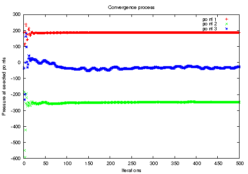
  • Create easy Gnuplot script named e.g. plotProbes which displays pressure development in three selected points:


    # Gnuplot script file for plotting data from file "probes.dat"
    set title "Convergence process"
    set xlabel "Iterations"
    set ylabel "Pressure at selected points"
    plot  "postProcessing/probes/0/p" using 1:2 title 'point 1', \
          "postProcessing/probes/0/p" using 1:3 title 'point 2', \
          "postProcessing/probes/0/p" using 1:4 title 'point 3'
    pause mouse


  • Run the script:
    # gnuplot plotProbes
openfoam tutorial motor bike probe locations

Figure: OpenFOAM tutorial motor bike. Pressure distribution at three selected locations (1 – center of the mask, 2 – top point of helmet and 3 – motorbike tail)

Previous: Usage Up: TCFD-manual Next: Index
This is an automatically generated documentation by LaTeX2HTML utility. In case of any issue, please, contact us at info@cfdsupport.com.

TCFD\textregistered - Rescue List

  1. Check if the boundary conditions are reasonable (especially at the inlet and at the outlet).
  2. Check of all the units (physical dimensions) of all quantities are correct.
  3. Each TCFD\textregistered case consists of components. Check the number of components. Check if the components are connected, see the components graph (Figure [*]) in the Components settings.
  4. If you use automatic snappyHexMesh meshing, each component should be watertight. Check if all the components are watertight, see Section [*].
  5. All the interfaces between two components must fit perfectly. There is only one exception: in the periodic segment cases when using Mixing Plane, the interfaces may not fit in the circumferential direction. In all other cases the interfaces must fit perfectly.
  6. Check the axis of rotation. Axis point is recommended to be [0 0 0].
  7. Check the speed of rotation and its units. Check the direction of rotation (right hand rule).
  8. If using Mixing Plane BC, check the number of averaging intervals (mixing planes).
  9. Check if all the components and walls that should rotate are set as rotating.
  10. If you use a periodic case, check if the number of segments is correct.
  1. Check if the mesh dimensions are set correctly (mm, m, km, …). TCFD\textregistered solvers use always meters.
  2. Is the mesh OK also visually?
  3. In the report check the y+ values.
  4. If you use automatic snappyHexMesh meshing – check if the internal points are really inside the components (Otherwise the “inverse” volume is meshed).
  5. If you use automatic snappyHexMesh meshing – check if the background mesh is reasonable fine. At the beginning a reasonable background mesh cell size is the impeller diameter divided by 75.
  6. Does the background mesh cell size follow the dimensions of the input geometry?
  7. Check if all the initial values for all quantities are reasonable.
  8. If you use periodic segment case – check if the periodic patches (rotationAMI type) fit perfectly.
  9. Check the number of iterations or simulation time is reasonable – simulation has to be converged. Sometimes Convergence Check utility may stop the simulation too soon. Check it in the report, the quantities should be steady (converged)
  10. If your issue is still unresolved, please contact us at support@cfdsupport.com. The best way to do that is sharing the complete case to our technical support. If your case can not be shared for any reason – please send us the detailed case description and zipped logRun folder.