1

Previous: Using blockMesh generator Up: Using blockMesh generator Next: Running blockMesh

This is an automatically generated documentation by LaTeX2HTML utility. In case of any issue, please, contact us at info@cfdsupport.com.

File blockMeshDict

  • Let us go through the file:
    # less $FOAM_RUN /cavity/system/blockMeshDict
    /*--------------------------------*- C++ -*----------------------------------*\
    | =========                 |                                                 |
    | \\      /  F ield         | OpenFOAM: The Open Source CFD Toolbox           |
    |  \\    /   O peration     | Version:  dev                                   |
    |   \\  /    A nd           | Web:      www.OpenFOAM.com                      |
    |    \\/     M anipulation  |                                                 |
    \*---------------------------------------------------------------------------*/
    FoamFile
    {
        version     2.0;
        format      ascii;
        class       dictionary;
        object      blockMeshDict;
    }
    // * * * * * * * * * * * * * * * * * * * * * * * * * * * * * * * * * * * * * //
    
  • Header of OpenFOAM file
    convertToMeters 0.1;
    
  • Parameter convertToMeters allows the whole mesh scaling
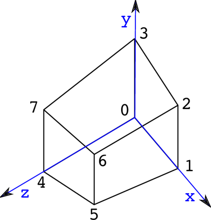
     

blockMesh cartezian numbering verticies

Figure: A general blockMesh hex numbering.

  • vertices        
    (
        (0 0 0)
        (1 0 0)
        (1 1 0)
        (0 1 0)
        (0 0 0.1)
        (1 0 0.1)
        (1 1 0.1)
        (0 1 0.1)
    );
    
  • In section vertices there are written coordinates (points) of blocks of the mesh


    blocks          
    (
        hex (0 1 2 3 4 5 6 7) (20 20 1) simpleGrading (1 1 1)
    );
    
  • In section blocks there are defined all blocks of the mesh; hex(0 1 2 3 4 5 6 7) (20 20 1) means hexahedral of eight vertices (0-7) according to order in vertices. The block is divided into 20 x 20 x 1 cells
  • Parameter simpleGrading allows refinement setting in the local directions (x y z); (1 1 1) = means uniform distribution in all directions
    The local directions for the block hex(0 1 2 3 4 5 6 7) are defined by following point couples:
    • direction x is defined by points with labels 0 -> 1
    • direction y is defined by points with labels 0 -> 3
    • direction z is defined by points with labels 0 -> 4


    edges           
    (
    );
    
  • In section edges there are defined curved edges connecting block vertices
  • If nothing is specified here, blockMesh uses lines


    boundary
    (
        movingWall
        {
            type wall;
            faces
            (
                (3 7 6 2)
            );
        }
        fixedWalls
        {
            type wall;
            faces
            (
                (0 4 7 3)
                (2 6 5 1)
                (1 5 4 0)
            );
        }
        frontAndBack
        {
            type empty;
            faces
            (
                (0 3 2 1)
                (4 5 6 7)
            );
        }
    );
    
  • In section boundary there are defined types of boundaries


    mergePatchPairs 
    (
    );
    
    // ************************************************************************* //
    
  • In section mergePatchPairs there can be defined boundaries to be merged

Examples

The selected tutorials are used for illustration as in the documentation of the Turbo Unwrap filter. The filter transforms only cell data and if point data are needed (e.g. for usage of the Glyph filter), it is necessary to apply the Cell data to point data filter.

NOTE: the filters tend to disappear from their categories after use. This is a feature of ParaView, which moves the last used filter menu item into Filters > Recent. That list is, however, limited. Nevertheless, all filters are alwys accessible through the Filters > Search option.

Previous: Boundary condition: Outlet Up: TCFD – GUI Setup Next: Simulation controls
This is an automatically generated documentation by LaTeX2HTML utility. In case of any issue, please, contact us at info@cfdsupport.com.

Initial conditions

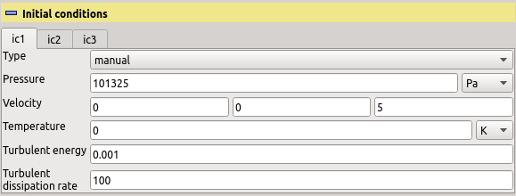
The initial conditions are set for each speedline independently. Typical setup is displayed in Figure [*]. There are two ways how to initialize the fields for the calculation: manually and by field mapping. The manual way means specifying uniform initial value for individual fields that will be solved for.
  • The entry “Pressure” sets a constant value of initial pressure throughout the computational domain. The solver will then iteratively improve this initial estimate.
  • The entry “Velocity” sets a constant value of initial velocity throughout the computational domain. It is recommended that the initial flow follows the overall expected flow direction, typically along the rotation axis.
  • The entry “Temperature” sets a constant value of initial temperature throughout the computational domain.
  • The entry “Turbulent energy” sets a constant value of initial turbulent energy $ k$ throughout the computational domain. This is only needed when using $ k-\omega$ or $ k-\epsilon$ turbulence model.
  • The entry “Turbulent dissipation” sets a constant value of initial turbulent dissipation rate $ \epsilon$ throughout the computational domain. This is only needed when using $ k-\epsilon$ turbulence mode.
  • The entry “Turbulent dissipation rate” sets a constant value of initial turbulent dissipation rate $ \omega$ throughout the computational domain. This is only needed when using $ k-\omega$ turbulence mode.
On the contrary, when using the mapped initial condition, the fields will be initialized by results from some other OpenFOAM calculation. The meshes of the old and the new calculation need to be very similar and the boundary patches in both cases must have the same names.
  • The entry “Source case” is a path to a directory with a completed TCFD (or generally OpenFOAM) calculation to be used.
  • If the selected case is a valid OpenFOAM case, the selection list “Source time” can be used to select a particular (stationary) time result directory from the chosen case.
cfd processor TCFDSource initial condition compressible
cfd processor TCFDSource initial condition mapped

Figure: Plugin TCFDSource – initial conditions: Manual (top) and mapped (bottom) variants.