1

Previous: File blockMeshDict Up: Using blockMesh generator Next: Test case setup
This is an automatically generated documentation by LaTeX2HTML utility. In case of any issue, please, contact us at info@cfdsupport.com.

Running blockMesh

  • Each application has its help:
    # blockMesh -help
    Usage: blockMesh [OPTIONS]                                                                                                        
    options:                                                                                                                          
      -blockTopology    write block edges and centres as .obj files                                                                   
      -case <dir>       specify alternate case directory, default is the cwd                                                          
      -dict <file>      specify alternative dictionary for the blockMesh description                                                  
      -noClean          keep the existing files in the polyMesh                                                                       
      -noFunctionObjects                                                                                                              
                        do not execute functionObjects
      -region <name>    specify alternative mesh region
      -srcDoc           display source code in browser
      -doc              display application documentation in browser
      -help             print the usage
    
    Block description
    
      For a given block, the correspondence between the ordering of
      vertex labels and face labels is shown below.
      For vertex numbering in the sequence 0 to 7 (block, centre):
        faces 0 (f0) and 1 are left and right, respectively;
        faces 2 and 3 are bottom and top;
        and faces 4 and 5 are front the back:
    
               4 ---- 5
          f3   |\     |\   f5
          |    | 7 ---- 6   \
          |    0 |--- 1 |    \
          |     \|     \|    f4
          f2     3 ---- 2
    
                f0 ----- f1
    
    
    Using: OpenFOAM-dev (see www.OpenFOAM.org)
    Build: dev-e2ccbbbb
    
  • Parameter -help displays options of each application
  • Run blockMesh application in test case directory:
    # cd $FOAM_RUN /cavity
    # blockMesh
  • Application checkMesh displays important information about the generated mesh:
    # checkMesh

Periodic (Cyclic) Family of Boundary Conditions

Periodic (Cyclic) boundary conditions are very strong tool in CFD. Meshes of different elements can be inter-connected. The boundaries have to be of equal shape and equal area. The transformation can be rotational, translational or noOrdering.

Previous: Initial conditions Up: TCFD – GUI Setup Next: Post-processing
This is an automatically generated documentation by LaTeX2HTML utility. In case of any issue, please, contact us at info@cfdsupport.com.

Simulation controls

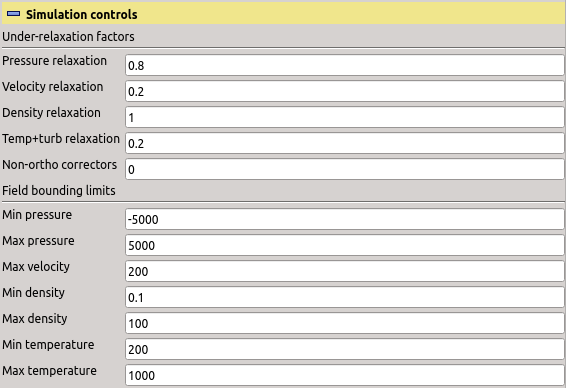
The under-relaxation factors and (in advanced mode) the number of non-orthogonal correctors can be changed in this section, see figure [*]. Depending on the selection of incompressible or compressible calculation, the section offers modification of some or all of the following factors: pressure, velocity, density, temperature and turbulence. If available, the temperature and turbulence relaxation factors are always considered equal. The defaults are concisely summarized in the table [*].
  • The entry “Non-ortho correctors” sets the number of non-orthogonal correctors. Should be increased up to $ 3$ if simulation shows large time step continuity error.
  • The entry “Minimal pressure” sets the lower bound for the pressure. If there is a cell with a lower pressure after a solver iteration it will be adjusted to this value. This bounding can help in the beginning of the solution process, when the fields wildly oscillate iteration-to-iteration before stabilization. The minimal and maximal pressure bounds are given in numerical units, which is Pa in compressible calculation and $ \mathrm{Pa/(kg/m^3)} = \mathrm{m^2/s^2}$ in incompressible calculation, and in both cases without contribution of the reference pressure.
  • The entry “Maximal pressure” sets the upper bound for the pressure.
  • The entry “Maximal velocity” sets the upper bound for the magnitude of the velocity. Larger vectors are scaled to this magnitude.
  • The entry “Minimal temperature” sets the lower bound for the temperature. This is only available for the compressible setup.
  • The entry “Maximal temperature” sets the upper bound for the temperature. This is only available for the compressible setup.
  • The entry “Minimal density” sets the lower bound for the density. This is only available for the compressible setup.
  • The entry “Maximal density” sets the upper bound for the density. This is only available for the compressible setup.
Table: Plugin TCFDSource – default relaxation factors for all possible setups. The compressible subsonic setup is used for fans, the compressible transonic setup is used for compressors and compressible turbines.
 incompressiblecompressible subsoniccompressible transonic
pressure0.20.30.8
velocity0.50.70.2
density0.011.0
temperature0.50.2
turbulence0.20.50.2
cfd processor TCFDSource relaxation factors

Figure: Plugin TCFDSource – simulation controls: relaxation factors and bounding limits.