Previous: geometry Up: SnappyHexMesh mesh Next: snapControls
This is an automatically generated documentation by LaTeX2HTML utility. In case of any issue, please, contact us at info@cfdsupport.com.
castellatedMeshControls
This block defines parameters relevant for the first phase of meshing, i.e., the castellated phase:
maxLocalCells 500000;
- maxLocalCells – max number of cells per processor during refinement
maxGlobalCells 2000000;
- maxGlobalCells – max number of all cells before cell removal
minRefinementCells 5;
- minRefinementCells – the surface refinement loop might spend lots of iterations refining just a few cells, to avoid that cell refinement procedure is stop if the number of cells to be refined is less then this value
maxLoadUnbalance 0.10;
- maxLoadUnbalance – maximum processor imbalance during refinement, i.e., if the number of vertices on one processor differs from average number of vertices on another processor by more than maxLoadUnbalance
 , then re-balancing algorithm is performed
nCellsBetweenLevels 1;
- nCellsBetweenLevels – number of cells between different refinement levels, see Figure

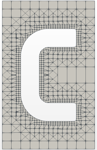
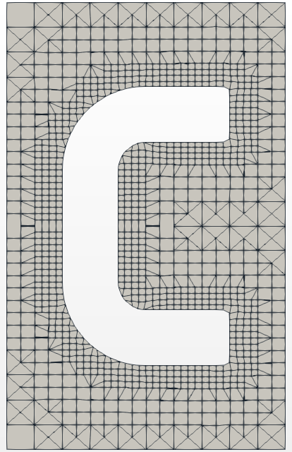
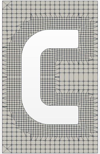
Figure: nCellsBetweenLevels: 1 – 4 – 7.
features ( { file "C-fine.eMesh"; level 0; } { file "F-fine.eMesh"; level 4; } { file "D-fine.eMesh"; level 3; } );- features block defines an explicit feature edge refinement
- Feature edges (*.eMesh files) can be generated by the surfaceFeatureExtract utility which setup is defined in system/surfaceFeatureExtractDict file:
C-fine.stl { extractionMethod extractFromSurface; extractFromSurfaceCoeffs { // Mark edges whose adjacent surface normals are at an angle less // than includedAngle as features // - 0 : selects no edges // - 180: selects all edges includedAngle 130; } writeObj yes; } - To generate these edges run:
# surfaceFeatureExtract - The feature edges can be visualized in ParaView by opening *_edgeMesh.obj in constant/extendedFeatureEdgeMesh directory
C { level (2 2); patchInfo { type wall; } } F { level (2 2); gapLevelIncrement 2; patchInfo { type wall; inGroups (FD); } } D { level (2 2); gapLevelIncrement 2; patchInfo { type wall; inGroups (FD); } } - Feature edges (*.eMesh files) can be generated by the surfaceFeatureExtract utility which setup is defined in system/surfaceFeatureExtractDict file:
- refinementSurfaces – includes levels of refinement, patch type and group name (optionally) for the given geometry part (from geometry section)

Figure: Labeling of cell levels.
- level – Specifies two levels for every surface. The first number is the minimum level – every cell intersecting a surface gets refined up to the minimum level. The second number is the maximum level. All background mesh cells holds level
 (see Figure
  ). See an example of different levels in Figure
- patchInfo block holds information about a type of a boundary and optionally can define groups for selected patches
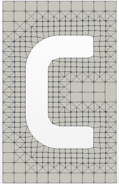
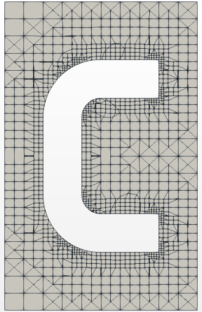
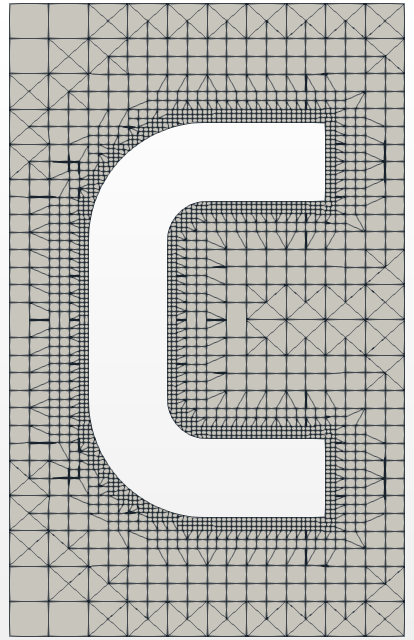
Figure: levels: (1 1) – (1 3) – (3 3).
resolveFeatureAngle 60;
- resolveFeatureAngle – feature angle refinement, it applies maximum level of refinement to cells that can see intersections whose angle exceeds this value.
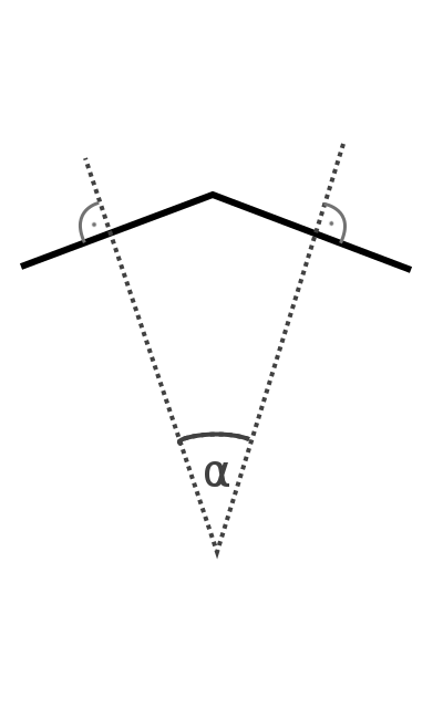
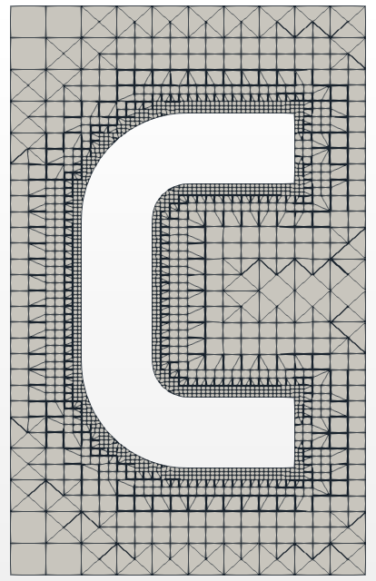
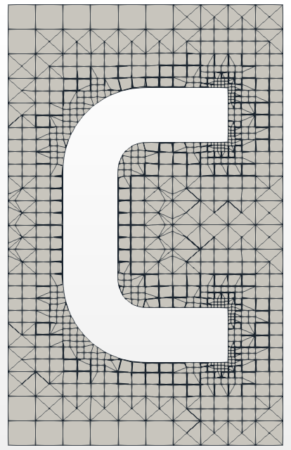
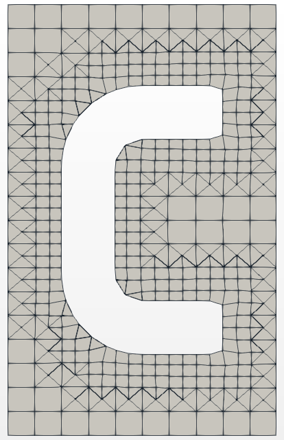
Figure: resolveFeatureAngle: 10 – 45 – 100.
refinementRegions { disk { mode distance; levels ((0.01 6)(0.05 3)); } }- refinementRegions – allows to define two types of refinement:
- inside – refinement level inside the (closed) object:
levels ((1E15 4))
only the second number is relevant, the first number is not read - distance – refinement level with respect to the distance from the object:
levels ((0.001 3) (0.01 2) (0.1 1))
locationInMesh (-0.111 0.0001 0.0001);
- inside – refinement level inside the (closed) object:
- locationInMesh – defines the part of the mesh which is not removed, the point must be placed inside a cell
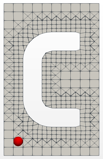
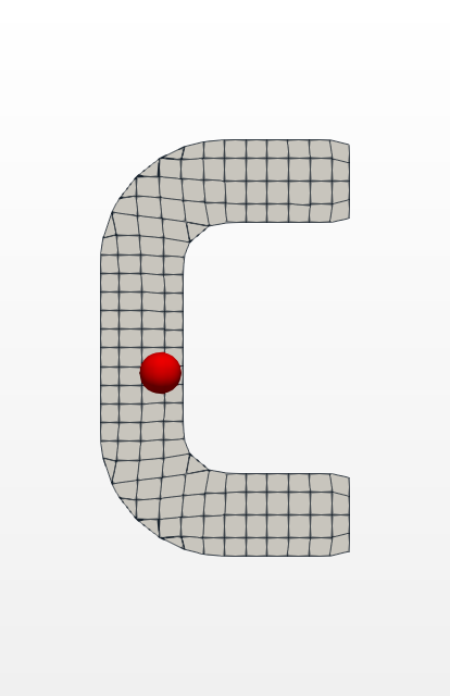
Figure: locationInMesh: outside – inside.
allowFreeStandingZoneFaces true;
- allowFreeStandingZoneFaces Allowing zone faces that share the same owner and neighbour cell zone. Not used if there are no faceZones.
Previous: geometry Up: SnappyHexMesh mesh Next: snapControls


