Previous: Clean the Shells and Up: Explode & Clean the Next: Create the inlet and
This is an automatically generated documentation by LaTeX2HTML utility. In case of any issue, please, contact us at info@cfdsupport.com.
Completing the Valve Plug Body
- Use following procedure to create missing middle part o of a valve plug.
- At first make one line connecting the lower and upper part inner diameter.
- Rotate this line around the Y axis.
- The first point of the new line has its Cartesian coordinates (0, 0.0113, 0.012213). This point can be created by clicking New Entity > Basic > Point as it is shown in the picture
 .
. - BTW: You do not need create a new point. You can use an existing point. Just during the creation of a new line select a point with mouse.

Figure: Vertex 1 construction
- The second point of the line lies on the “inner edge of upper part” and this is a point with the largest Z coordinate.
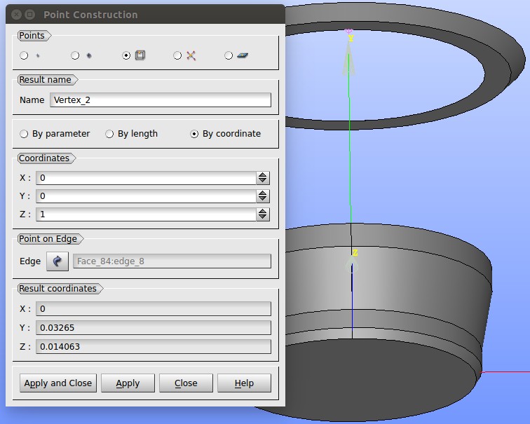
- To create the second point, navigate to New Entity > Basic > Point. The window “Point Construction” appears (see figure
 ).
). - In the new window select “point on a box edge” icon in Points row. Type a new vertex name into Result Name or you can leave the default name here. Select “By coordinate” and set Z coordinate to 1, leave 0 for others. Select the top inner circle edge in “Point on Edge” field and click “Apply and Close” and the second vertex is created.

Figure: Vertex 2 construction
- Two points for creating a line are ready now.
- Create a line from Vertex_1 to Vertex_2.
- Navigate to New Entity > Basic > Line and the window “Line Construction” appears (see figure
 ).
). - Select Vertex_1 and Vertex_2 and click “Apply and Close“.

Figure: Line Construction
- Now make a revolution of the line around the Y axis.
- Navigate to New Entity > Generation > Revolution.
- The window “Construction by Revolution” appears (see figure
 ).
). - Select Line_1 as an object of revolution. Select OY as an axis. Set an angle to 360
 .
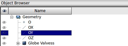
. - OY can be found at the top of the Object Browser – see figure
 ).
). - Finish by clicking Apply and Close.
- Vertex_1 and Vertex_2 and click “Apply and Close“.

Figure: OY in the Object Browser

Figure: Construction by revolution
- Now the revolution that connects the lower and the upper part of the plug is created.
- It is necessary to merge the upper part, the lower part and the new revolution into a single shell or compound.
- It is useful to create rather a shell than a compound. A shell is more strict on the model quality than a compound – especially regarding fittings of edges and faces. NOTE: If a shell can be created then the model is likely o.k.
- Select all the valve plug model and create a shell (see figure
 ) – in the menu open New Entity > Build > Shell.
 - Now, save your progress.
- BTW: The current state can be loaded anytime as an original file: “part2.hdf“.

Figure: Valve Plug – a shell construction


