Previous: General settings Up: TCFD – GUI Setup Next: Physics
This is an automatically generated documentation by LaTeX2HTML utility. In case of any issue, please, contact us at info@cfdsupport.com.
Simulation
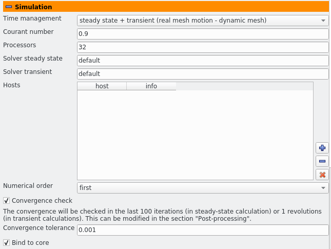
- The calculation mode can be chosen from the drop-down list “Time management”. Here one can choose between a simple steady-state calculation, or its combination with some of the transient extensions, which will start from the precomputed steady-state results. The options are a classical transient calculation with mesh motion, where all Mixing planes are replaced by face-weighted interpolation through AMI, and a “semi-transient” variant which solves transient equations, but the mesh is static and the rotation is simulated by the MRF method, as in the case of steady-state calculation.
- When transient mode is chosen, it is possible to give the maximal value of the “Courant number” throughout the simulation domain. Values above 1.0 should be used only with extreme caution.
- The entry “Processors” specifies number of processes used to run the mesher and the solver. OpenFOAM uses MPI (Message Passing Interface) for communication of the processes.
- The entry “Solver steady state” (advanced) allows you to use a user-compiled solver within the steady-state TCFD simulation.
- When transient mode is chosen, the entry “Solver transient” (advanced) allows you to use a user-compiled solver within the transient TCFD simulation.
- The table “Hosts” (advanced) can be used in conjunction with the “Processors” entry to schedule the running of the parallel jobs. This table contains nodes, on which the parallel processes will be launched. The total number of processes given by “Processors” is evenly divided between the nodes. A new node is added by the plus button. This is by default the “localhost” node, but the word “localhost” in the first column can be edited (double-click to enable editing) to any other host name or IP address. The simple local network information provided by the system utility “getent” is then shown in the second column. If the node is unknown, the table row will turn red. Such nodes must be deleted, or the execution will fail. There are several restrictions on the usage of remote nodes:
- All nodes must be accessible from the workstation where ParaView runs without password for the current user (i.e. using the public key authentication), and the same must be true for access between the nodes.
- The MPI and OpenFOAM installations on the workstation and all the nodes must be identical. Ideally, there is just one installation on a shared network file system.
- The OpenFOAM case directory is written on a shared network file system, so that it is accessible both to the front-end workstation used for solution management via ParaView and to the remote calculation nodes.
- The entry “Numerical order” sets the discretization order of the convection term. All calculation should converge with the first order. The second order generally provides more accurate results, but the simulations are often less stable and may require better meshes or other tuning.
- The switch “Convergence check” enables and disables automatic convergence check. If disabled, then CFD processor will always run the solver for specified amount of iterations. If enabled, then the solution of a particular point can terminate earlier. Two other parameters control the convergence checking: the “Convergence tolerance” and “Averaging window” (or “Transient window” in transient phase of the calculation). The calculation is deemed converged once all the following criteria hold:


 In these expressions
Figure: Plugin TCFDSource – simulation settings.
Previous: General settings Up: TCFD – GUI Setup Next: Physics


![Node38 7 [*]](https://www.cfdsupport.com/wp-content/uploads/2022/02/crossref.png)