Previous: Reference frames Up: TCFD – GUI Setup Next: Speedlines
This is an automatically generated documentation by LaTeX2HTML utility. In case of any issue, please, contact us at info@cfdsupport.com.
Components
![Node41 7 [*]](https://www.cfdsupport.com/wp-content/uploads/2022/02/crossref.png) .
The computational domain can be split into any number of sub-domains – the components. Components are meshed individually, they can be individually set as rotating and individually postprocessed.
Each domain can have any number of inlets and outlets and can be connected to any number of other components through inlet or outlet interfaces. There can be just one inlet interface from component A to component B, as well as just one outlet component. As the names “inlet” and “outlet” interface suggest, they should be used with consideration of the anticipated direction of flow. This pre-orientation is a requirement between rotating and non-rotating components, where the Mixing plane will be used. Between co-rotating components it is not necessary, as the cyclicAMI interface used in those cases is symmetrical.
At any time, the current topology of the components is graphically represented in the component graph at the end of “Components” section. A sample auto-generated component graph is displayed in Figure
.
The computational domain can be split into any number of sub-domains – the components. Components are meshed individually, they can be individually set as rotating and individually postprocessed.
Each domain can have any number of inlets and outlets and can be connected to any number of other components through inlet or outlet interfaces. There can be just one inlet interface from component A to component B, as well as just one outlet component. As the names “inlet” and “outlet” interface suggest, they should be used with consideration of the anticipated direction of flow. This pre-orientation is a requirement between rotating and non-rotating components, where the Mixing plane will be used. Between co-rotating components it is not necessary, as the cyclicAMI interface used in those cases is symmetrical.
At any time, the current topology of the components is graphically represented in the component graph at the end of “Components” section. A sample auto-generated component graph is displayed in Figure ![Node41 7 [*]](https://www.cfdsupport.com/wp-content/uploads/2022/02/crossref.png) .
If one of the simulation types stator, virtualTunnel, propeller or windTurbine is chosen, checkbox “Bounding box” appears in the ”Components” section. Using this feature, TCFD can be used for simulations of external flows. If “Bounding box” is checked, axis oriented box is added, which works as a virtual wind tunnel, and another three entries will show up (Figure
.
If one of the simulation types stator, virtualTunnel, propeller or windTurbine is chosen, checkbox “Bounding box” appears in the ”Components” section. Using this feature, TCFD can be used for simulations of external flows. If “Bounding box” is checked, axis oriented box is added, which works as a virtual wind tunnel, and another three entries will show up (Figure ![Node41 7 [*]](https://www.cfdsupport.com/wp-content/uploads/2022/02/crossref.png) ):
):
- “Flow direction” entry determines the direction of the flow through the bounding box. The actual velocity vector might slightly differ from this direction (depends on the type of the inlet boundary condition), as purpose of “Flow direction” is to decide, which patches of the box will be inlet and outlet.
- “Bounding box point 1” sets the coordinates of the one vertex of the box.
- “Bounding box point 2” sets the coordinates of the opposite vertex.
![Node41 7 [*]](https://www.cfdsupport.com/wp-content/uploads/2022/02/crossref.png) ). After the bounding box is added, its patches will appear in the “Patches table”.
). After the bounding box is added, its patches will appear in the “Patches table”. 
Figure: Plugin TCFDSource – component setup, bounding box entries.
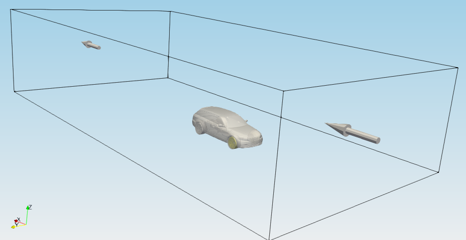
Figure: Plugin TCFDSource – bounding box representation in RenderView.
The number of components is controlled by the slider (or edit field) “Number of components”. When the number of components changes, the number of panels in this section and also in the advanced mesh properties panels is adjusted accordingly. Every component needs a water-tight boundary geometry divided into non-overlapping segments or a ready-to-use mesh. Currently there are three options for input of component mesh. The “Components” includes following parameters:
- The entry “Scale factor” sets the scale of the length units to be used when processing the input geometry and some other form entries (namely “Origin”, “Background mesh size”, “Internal point”, “Wheel diameter”, blade clearance and distances to interfaces). If “1” is given, then CFD Processor assumes that all lengths and point coordinates are in meters, whereas if (e.g.) “0.001” is given, it is assumed that they are in millimeters. This setting is global: It is not possible to set different length scales for the geometry and for the form entries, or to have individual geometry files in different scales.

- Directory with STL files – The directory must contain ASCII STL files which, when merged, give rise to a water-tight boundary surface. Every STL corresponds to an OpenFOAM patch (with a name taken from the name of the STL file), except for interface patches which are ultimately renamed to reflect which components they connect. Note that the STL file names should consist only of alpha-numerical characters, dashes and underscores.
- Multi-solid STL file – The input is a single ASCII STL file containing multiple solids. Every solid must have a unique name within the STL file. That name will be used for naming the patch. Please make sure that the solid names consist only of alpha-numerical characters, dashes and underscores.
- External OpenFOAM mesh – The patches (and mesh) are taken from an already existing OpenFOAM mesh. The mesh creation step for this component will be skipped.
- External Fluent mesh – The patches (and mesh) are taken from an already existing mesh in MSH format. The mesh creation step for this component will be skipped. The MSH mesh reader is compatible both with the ASCII and binary formats.
- “Component name”, which sets the name of the component used in patch names and report.
- “Reference frame” sets a frame from “Reference frames” section. A rotating frame makes the whole component rotating (needed for all components containing impellers/propellers). A static frame makes the component stationary.
- “No. periodic segments”, which is used to set periodicity of a segment when simulating just a segment of the full wheel.
- inlet – Entry to the simulated machine, mostly to the first component.
- outlet – Exit from the simulated machine, mostly the last component.
- internalAMI – Internal non-conformal mesh interface. It is necessary to connect this interface to another “internalAMI” interface within the same component by right-clicking on the row and selecting the patch, see Figure
![Node41 7 [*]](https://www.cfdsupport.com/wp-content/uploads/2022/02/crossref.png) . This change will be indicated by a colour change of the rows.
. This change will be indicated by a colour change of the rows. - translationAMI – Periodic interface in simulation of a translationally symmetric domain. It is necessary to connect this interface to another “translationAMI” interface within the same component by right-clicking on the row and selecting the patch. This change will be indicated by a colour change of the rows.
- rotationAMI – Patches on the boundaries of a segment, which are (periodically) mapped to each other. It is necessary to connect this interface to another “rotationAMI” interface within the same component by right-clicking on the row and selecting the patch. This change will be indicated by a colour change of the rows.
- empty – Boundary in non-physical, artificial, dimension; used in two-dimensional simulations.
- symmetry – Special symmetry boundary condition for calculation of just a half of a perfectly symmetrical system. For compatibility reasons, using this boundary condition causes using segregated linear solver (instead of default coupled) for velocity. This has, in vast majority of cases, no influence on results.
- wall – General no-slip wall.
- wallSlip – General perfect-slip wall.
- hub – A specific type of wall.
- shroud – A specific type of wall.
- blade – A specific type of wall.
- bladePressureSide – A specific type of wall.
- bladeSuctionSide – A specific type of wall.
- bladeLeadingEdge – A specific type of wall.
- bladeTrailingEdge – A specific type of wall.
- bladeHubFillets – A specific type of wall.
- bladeShroudFillets – A specific type of wall.
- bladeCap – A specific type of wall.
- cutWater – A specific type of wall.
- inletInterface – Entry to other components, connected to some preceding component. It is necessary to connect this interface to a specific component by right-clicking on the row and selecting the component. This change will be reflected in the component graph.
- outletInterface – Exit from other components, connected to some following component. It is necessary to connect this interface to a specific component by right-clicking on the row and selecting the component. This change will be reflected in the component graph.
- freestreamInterface – For interfaces where both flow direction may occur, e.g., open propellers. It is necessary to connect this interface to a specific component where the same interface is defined by right-clicking on the row and selecting the component. This change will be reflected in the component graph. This type always imposes cyclicAMI boundary condition.
- A common approach is to assign the same frame (assigned to the whole component) to all patches in the component.
- For patches of type wall (wall, hub, blade*,…) a rotation can be individually set:
- Rotating frame can be assigned to define rotating patch
- Non-rotating frame can be assigned to define non-rotating patch
- Locked – all the patches of the same type uses the same levels of refinement.
- Unlocked – the patch can hold its own refinement levels independently.
- “Background mesh size”, which sets the basic cell size in the three directions for the rectangular background mesh (all cells will be such or smaller). Background mesh can be displayed in the RenderView by the adjacent checkbox.
- “Cylindrical mesh” requests the use of a cylindrical background mesh instead of the rectangular, see Figure
![Node41 7 [*]](https://www.cfdsupport.com/wp-content/uploads/2022/02/crossref.png) , and enables the following three parameters.
, and enables the following three parameters. - “Cylindrical radii”, which sets the parameters
 ,
,  and
and  of the cylindrical mesh,
 - “Cylindrical grading”, which sets the parameters
 , and
, and  of the cylindrical mesh and
 - “Cylindrical warp”, which sets the parameter
 of the cylindrical mesh.
 - “Internal point”, which specifies arbitrary internal point. This is needed by the mesher. Internal point can be displayed in the RenderView by the adjacent checkbox. When shown, it can be directly manipulated by mouse.
- “Wheel diameter” is a mandatory parameter only for the “fan” machine and is used for post-processing.
- “Use gap refinement” checkbox enables setting higher level of refinement then “max ref” value for meshing small gaps between different parts of the input geometry. It shows a new column in the Patches table. The minimum value is equal to “max ref” value.
- “Euler alpha/beta/gamma” can be used for rotation of the background mesh to achieve better alignment with the input geometry. It uses Eulers angles intrinsic (z-y’-z”) rotation convention.
- “Leading edge gap” is an optional parameter specifying distance between the leading edge of the blade and the adjacent interface (if any). When given, then the refinement level for leading edge STL surfaces will be calculated such that the gap contains at least 8 cells across.
- “Trailing edge gap” is an optional parameter specifying distance between the trailing edge of the blade and the adjacent interface (if any). When given, then the refinement level for trailing edge STL surfaces will be calculated such that the gap contains at least 8 cells across.
- “Blade cap gap”, commonly called “clearance” is the distance between the blade cap and the shroud. When given, then the refinement level for blade cap STL surfaces will be calculated such that the gap contains at least 8 cells across.
- “Use refinement regions” enables defining additional refinement regions:
- “Type” shape of the refinement regions (box, cylinder or sphere).
- “Mode” if the mesh refinement is applied inside or outside of the refinement region.
- “Level” level of refinement to be applied
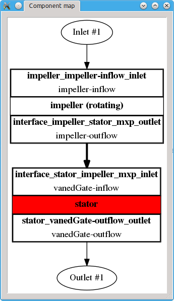
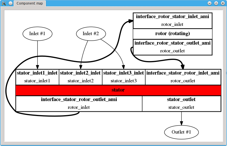
Figure: Plugin TCFDSource – two examples of the (detached) “component graph”. Left: Machine has linear topology with single inlet and single outlet. The fluid enters impeller component, then goes to stator component, where it leaves. Right: Machine has cyclic topology and multiple inlets, where first inlet has a unique boundary condition, while the other two have the same boundary condition. Here, the fluid enters stator component via one of the three inlets. The stator component can be left through a single outlet, or the fluid can flow through the rotor part first. The rotor can be skipped e.g. due to a leakage – fluid that goes through the leakage goes directly from inlet to outlet, without ever visiting rotor.
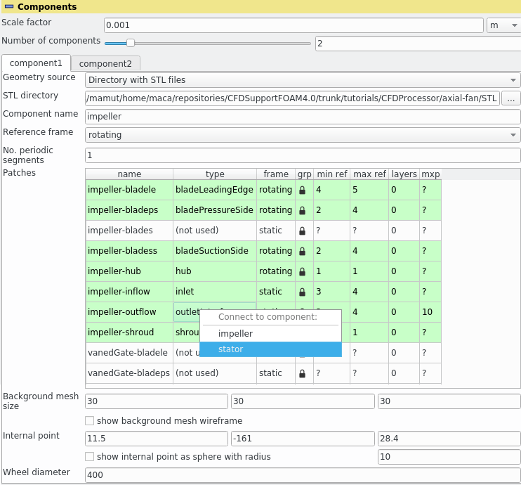
Figure: Plugin TCFDSource – component setup, displaying process of connection of components via interfaces.
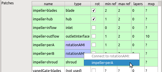
Figure: Plugin TCFDSource – component setup – connecting the internalAMI / translationAMI / rotationAMI patches.
![Node41 7 [*]](https://www.cfdsupport.com/wp-content/uploads/2022/02/crossref.png) ) displays all components and their interfaces. Thick arrows point always from inlet to outlet interface. If some interface is not available (or connected), the arrows become dashed and point elsewhere. This then indicates an invalid topology. All components must be connected into a single domain using the inletInterface/outletInterface pairs. The graph can be detached from the Properties panel by a double-click; this transfers it to a new window. The separated window stays by default on top of all other windows (this can be manually unselected in the window manager menu). Further double-click merges the window back into the panel, as does also closing the window in any other way. The colours in the graph correspond to colours of the individual components in RenderView, assuming the colouring by vtkBlockColors is chosen. The graph also displays all inlets and outlets, with inlet and outlet components assigned to them. In a valid setup, all inlets and outlets should have exactly one inlet boundary condition and outlet boundary condition, respectively, assigned to them. If some inlet/outlet lacks inlet/outlet boundary condition, its name becomes red. If some inlet/outlet has more than one inlet/outlet boundary condition, its name becomes red, and so do the inlet/outlet boundary condition arrows pointing to it.
) displays all components and their interfaces. Thick arrows point always from inlet to outlet interface. If some interface is not available (or connected), the arrows become dashed and point elsewhere. This then indicates an invalid topology. All components must be connected into a single domain using the inletInterface/outletInterface pairs. The graph can be detached from the Properties panel by a double-click; this transfers it to a new window. The separated window stays by default on top of all other windows (this can be manually unselected in the window manager menu). Further double-click merges the window back into the panel, as does also closing the window in any other way. The colours in the graph correspond to colours of the individual components in RenderView, assuming the colouring by vtkBlockColors is chosen. The graph also displays all inlets and outlets, with inlet and outlet components assigned to them. In a valid setup, all inlets and outlets should have exactly one inlet boundary condition and outlet boundary condition, respectively, assigned to them. If some inlet/outlet lacks inlet/outlet boundary condition, its name becomes red. If some inlet/outlet has more than one inlet/outlet boundary condition, its name becomes red, and so do the inlet/outlet boundary condition arrows pointing to it. Previous: Reference frames Up: TCFD – GUI Setup Next: Speedlines


