Next: Model setting without an Up: Alternative formulation Previous: Alternative formulation Contents Index
Running snappyHexMesh - Rotor Region
Utility snappyHexMesh refines background mesh in direction to the surface model, reading set-up from system/snappyHexMeshDict:
// Which of the steps to run
castellatedMesh true;
snap            true;
addLayers       true;

// Geometry. Definition of all surfaces. All surfaces are of class
// searchableSurface.
// Surfaces are used
// - to specify refinement for any mesh cell intersecting it
// - to specify refinement for any mesh cell inside/outside/near
// - to 'snap' the mesh boundary to the surface
geometry
{
    align-rot-guide.stl     {  type triSurfaceMesh;  name rotor_spiral_interface;       }
    shroud-rot.stl          {  type triSurfaceMesh;  name shroud_rot_wall;   }
    hub-rot.stl             {  type triSurfaceMesh;  name hub_rot_wall;      }
    blade-rot.stl           {  type triSurfaceMesh;  name blade_rot_wall;    }
    align-rot-draft.stl     {  type triSurfaceMesh;  name rotor_drafttube_interface;       }
};

// Settings for the castellatedMesh generation.
castellatedMeshControls
{

    // Refinement parameters
    // ~~~~~~~~~~~~~~~~~~~~~

    // If local number of cells is >= maxLocalCells on any processor
    // switches from from refinement followed by balancing
    // (current method) to (weighted) balancing before refinement.
    maxLocalCells 100000;

    // Overall cell limit (approximately). Refinement will stop immediately
    // upon reaching this number so a refinement level might not complete.
    // Note that this is the number of cells before removing the part which
    // is not 'visible' from the keepPoint. The final number of cells might
    // actually be a lot less.
    maxGlobalCells 2000000;

    // The surface refinement loop might spend lots of iterations refining just a
    // few cells. This setting will cause refinement to stop if <= minimumRefine
    // are selected for refinement. Note: it will at least do one iteration
    // (unless the number of cells to refine is 0)
    minRefinementCells 0;

    // Allow a certain level of imbalance during refining
    // (since balancing is quite expensive)
    // Expressed as fraction of perfect balance (= overall number of cells /
    // nProcs). 0=balance always.
    maxLoadUnbalance 0.10;

    // Number of buffer layers between different levels.
    // 1 means normal 2:1 refinement restriction, larger means slower
    // refinement.
    nCellsBetweenLevels 2;


    // Explicit feature edge refinement
    // ~~~~~~~~~~~~~~~~~~~~~~~~~~~~~~~~

    // Specifies a level for any cell intersected by explicitly provided
    // edges.
    // This is a featureEdgeMesh, read from constant/triSurface for now.
    // Specify 'levels' in the same way as the 'distance' mode in the
    // refinementRegions (see below). The old specification
    //      level   2;
    // is equivalent to
    //      levels  ((0 2));

    features
    (
        //{
        //    file "someLine.eMesh";
        //    //level 2;
        //    levels ((0.0 2) (1.0 3));
        //}
    );


    // Surface based refinement
    // ~~~~~~~~~~~~~~~~~~~~~~~~

    // Specifies two levels for every surface. The first is the minimum level,
    // every cell intersecting a surface gets refined up to the minimum level.
    // The second level is the maximum level. Cells that 'see' multiple
    // intersections where the intersections make an
    // angle > resolveFeatureAngle get refined up to the maximum level.

    refinementSurfaces
    {
        // patches
        shroud_rot_wall      {  level (4 5);  patchInfo { type wall; }  }
        hub_rot_wall         {  level (4 5);  patchInfo { type wall; }  }
        blade_rot_wall       {  level (5 5);  patchInfo { type wall; }  }

        // rotor boundaries
        rotor_spiral_interface          {  level (3 4);  patchInfo { type patch; }  }
        rotor_drafttube_interface          {  level (3 4);  patchInfo { type patch; }  }
    }

    // Feature angle:
    // - used if min and max refinement level of a surface differ
    // - used if feature snapping (see snapControls below) is used
    resolveFeatureAngle 30;


    // Region-wise refinement
    // ~~~~~~~~~~~~~~~~~~~~~~

    // Specifies refinement level for cells in relation to a surface. One of
    // three modes
    // - distance. 'levels' specifies per distance to the surface the
    //   wanted refinement level. The distances need to be specified in
    //   increasing order.
    // - inside. 'levels' is only one entry and only the level is used. All
    //   cells inside the surface get refined up to the level. The surface
    //   needs to be closed for this to be possible.
    // - outside. Same but cells outside.

    refinementRegions
    {
        //box1x1x1
        //{
        //    mode inside;
        //    levels ((1.0 4));
        //}
        //sphere.stl
        //{
        //    mode distance;
        //    levels ((1.0 5) (2.0 3));
        //}
    }

    // Mesh selection
    // ~~~~~~~~~~~~~~

    // After refinement patches get added for all refinementSurfaces and
    // all cells intersecting the surfaces get put into these patches. The
    // section reachable from the locationInMesh is kept.
    // NOTE: This point should never be on a face, always inside a cell, even
    // after refinement.
    locationInMesh (1.001 0 -1.001);

    // Whether any faceZones (as specified in the refinementSurfaces)
    // are only on the boundary of corresponding cellZones or also allow
    // free-standing zone faces. Not used if there are no faceZones.
    allowFreeStandingZoneFaces true;
}
- Lines 28-35 define the geometry using *.stl files of triSurfaceMesh type. The parameter nameassign a name to the given part of geometry.
- Lines 105-115 define a level of surface refinements and type of new patches.
Create the mesh running snappyHexMesh utility:
# snappyHexMesh
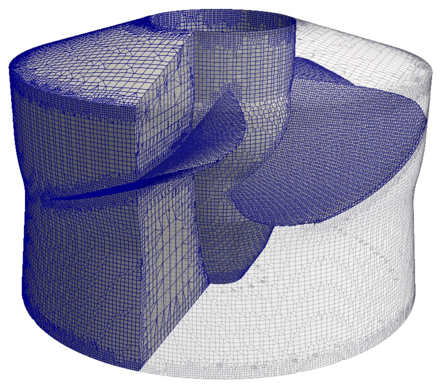
When finished, check the mesh running checkMesh and view the mesh in paraview:
# checkMesh -latestTime
# paraFoam

Figure: Kaplan turbine rotor region mesh view.
The final mesh is located in directory with the highest number.


