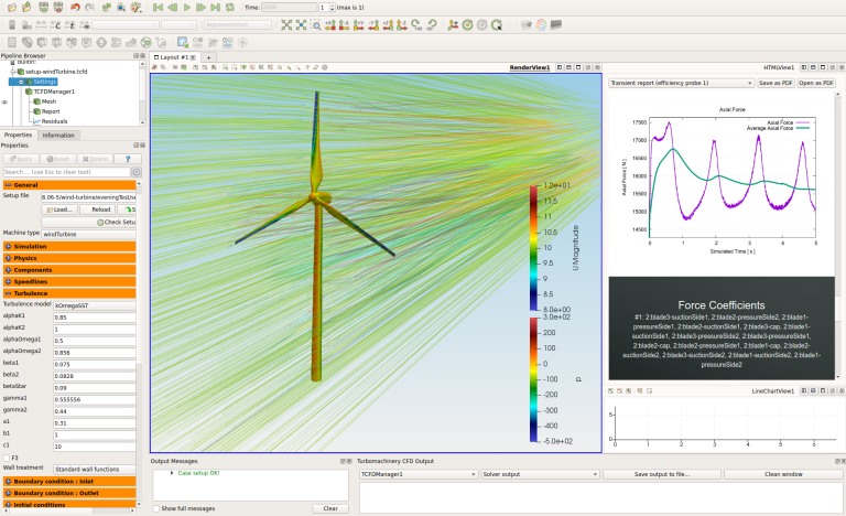
Wind Turbine CFD Simulation
This casy study shows a complex CFD analysis of wind turbine using simulation environment TCAE
FEA Simulation Report
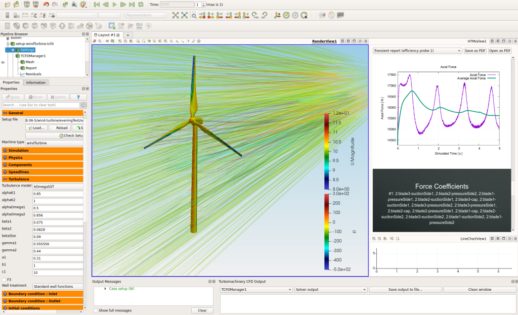
TCFD is automated workflow
CFD SUPPORT introduces the new generation of CFD simulations. TCFD brings an extreme increase of productivity to CFD simulations. TCFD is extremely popular project, because it successfully merged benefits of an open-source (perpetual, unlimited users, jobs, and cores, customizable, …) with benefits of commercial codes (professional support, well tested, ready for the industry, robust, accurate, automated, GUI, …).

TCFD is fully automated, it can run the whole workflow by a single command: data input, new case is written down, mesh is created, case is set-up, case is simulated, results are evaluated and the results report is written down. Both GUI and batch mode. Data in – data out. TCFD is mainly focused on supporting the engineers in their real value added work. TCFD is fully automated and the beauty of TCFD is that it is the user who decides how deep to dive into a CFD or not at all. And all the options remain open at the same time.
Test case - Wind Turbine
Wind turbines are manufactured in a wide range of vertical and horizontal axis types. The smallest turbines are used for applications such as battery charging for auxiliary power for boats or caravans or to power traffic warning signs. Slightly larger turbines can be used for making contributions to a domestic power supply while selling unused power back to the utility supplier via the electrical grid. Arrays of large turbines, known as wind farms, are becoming an increasingly important source of intermittent renewable energy and are used by many countries as part of a strategy to reduce their reliance on fossil fuels. One assessment claimed that, as of 2009, wind had the “lowest relative greenhouse gas emissions, the least water consumption demands and… the most favourable social impacts” compared to photovoltaic, hydro, geothermal, coal and gas. Source: Wikipedia https://en.wikipedia.org/wiki/Wind_turbine
Preprocessing
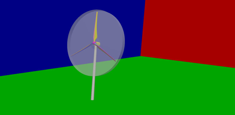
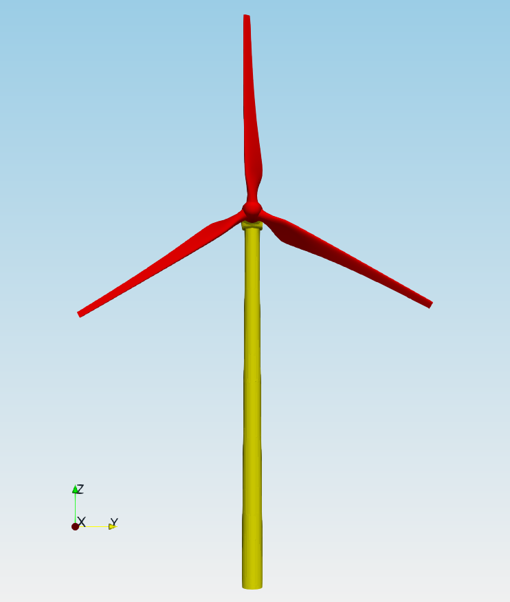
We started with a CAD model of Wind Turbine in file format STEP. For a professional CFD simulation, the original STEP file is usually too complex and therefore certain preprocessing work has to be done. Using an open-source software Salome, the model is simplified and cleaned. Some tiny and problematic parts are removed. The final surface model is made waterproof. An artificial “cylinder” surrounding the propeller is created, because of the propeller rotation. Another artificial objects is a “bounding box”, which will works as a virtual wind tunnel (domain boundary), so one can prescribe the boundary conditions. Finally, 2D surface meshes are generated to fit the CAD surface in an acceptable way. Individual STL files, that define the surfaces of the aircraft, bounding box and cylinder are exported. Remember, the preprocessing is extremely important for each CFD workflow. Preprocessing always limits the CFD results and sets the expectations.
Input data
The surface model data in .stl file format together with physical inputs are loaded in TCFD. Other option would be loading an external mesh in OpenFOAM® mesh format, or loading an MSH mesh format (Fluent mesh format). This CFD methodology employs a multi component approach, which means the model is split into a certain number of regions. In TCFD each region can have its own mesh and individual meshes comunicate via interfaces.
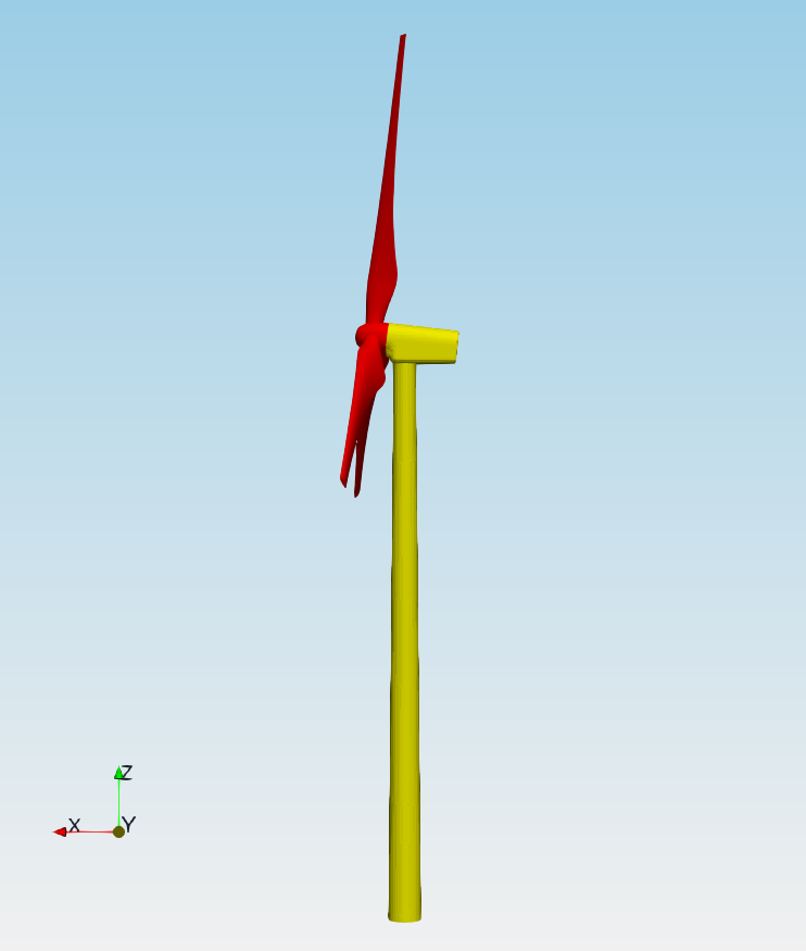
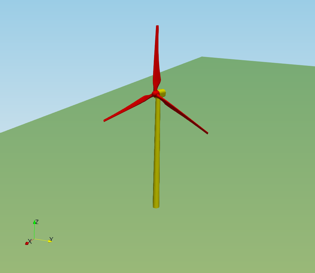
Graphical interface
Mesh
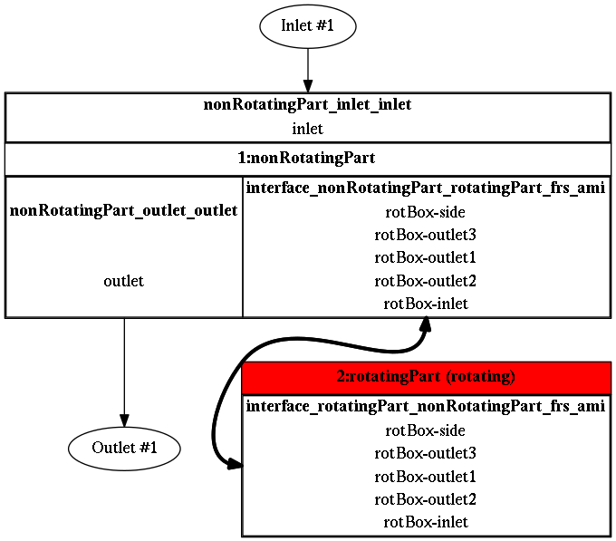
In this particular case, the simulation model is split into two components. The Propeller in cylinder and the rest of the domain. Each component has its own mesh. All the meshes are created automatically for each component within snappyHexMesh. Any number of model components is allowed.
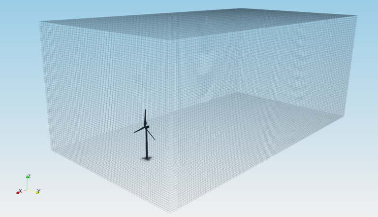
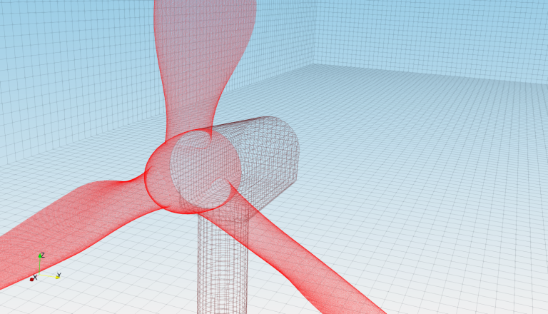
The component graph
Any project simulated in TCFD has its component graph. The component graph shows how the components are organized – the model topology. What is the inlet, the outlet and how the components are connected via interfaces.
CFD Simulation Set-up
- Incompressible & Compressible flow model
- Steady-state flow model
- Medium: Air
- Viscosity: μ = 1.831e-5 [Pa.s]
- Flow Velocity: 10 [m/s]
- Viscosity: μ = 1.831e-5 [Pa.s]
- Interface: freestream - solid body motion (no averaging)
- Turbulence Model: k-ω SST
- Mesh: hexadominant snappyHexMesh
- Mesh Cells: 14,724,069
- Mesh Average y+ (full/segment): 126 [-]
- CPU time (steady-state): 78 [core.hours]
For more details of CFD Simulation Set-up see TCFD Manual.
Running CFD Simulation
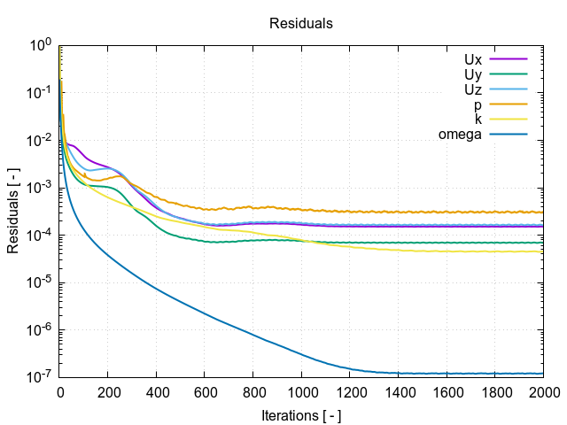
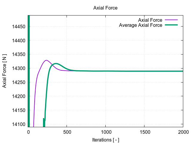
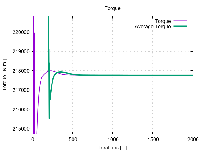
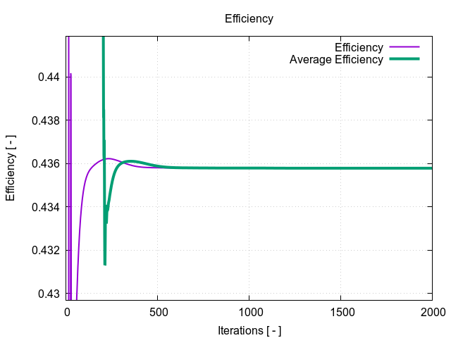
The simulation can be run on any number of parallel processors. Immediately after the simulation is started, the user can follow the progress of all the important quantities in a HTML report: flow rates, residuals, efficiency, torque, pressure difference and many others. These run-time functions give the user valuable information of the simulation convergence and also the availability to stop the simulation before its expected end.
Please contact us for further information.
Download TCAE Tutorial - Wind Turbine
File name: wind-turbine-TCAE-Tutorial-21.09.zip
File size: 23 MB
Tutorial Features: CFD, FEA, FSI, TCAE, TMESH, TCFD, TFEA, SIMULATION, FDA PUMP, RADIAL PUMP, CENTRIFUGAL PUMP, TURBOMACHINERY, INCOMPRESSIBLE FLOW, DEFORMATION, DISPLACEMENT, STRESS, MODAL ANALYSIS, INCOMPRESSIBLE, RANS, BLOOD FLOW, STEADY-STATE, AUTOMATION, WORKFLOW, RADIAL FLOW, FULL IMPELLER, SNAPPYHEXMESH, NETGEN, 3 COMPONENTS, RPM=3500, R=30mm

