
Potsdam Propeller CFD Simulation Benchmark
This study shows a complex CFD analysis and validation of Potsdam propeller test case
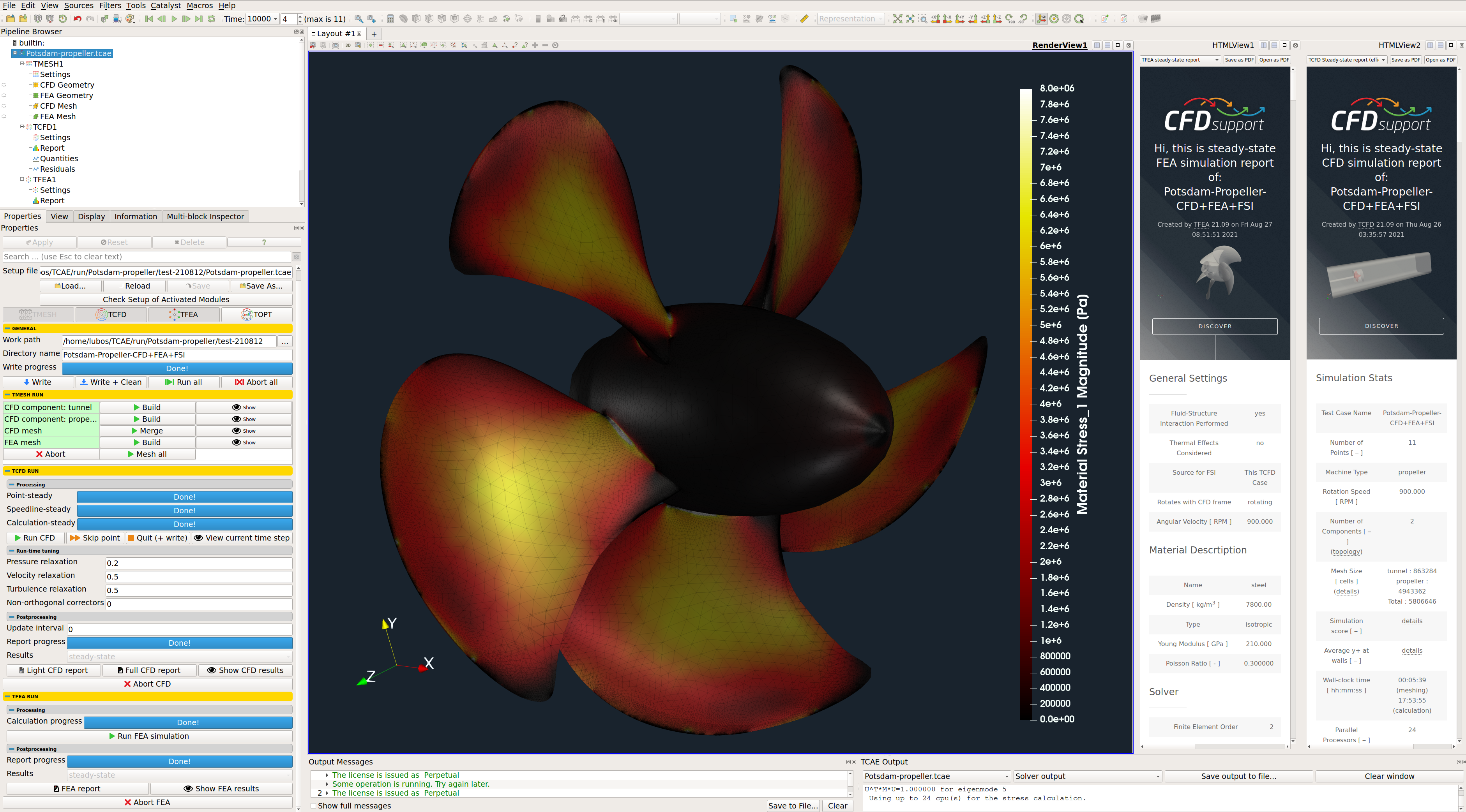
Potsdam Propeller TCFD Simulation Validation Benchmark
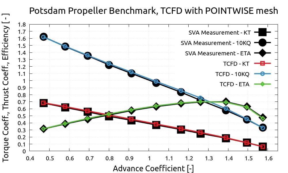
This report presents the benchmark validation of CFD simulation results of the Potsdam Propeller Test Case (PPTC), using TCFD with POINTWISE mesh. PPTC is a marine propulsor that was extensively measured by SVA Potsdam and related data were published [1], [2], [3]. The aim of this benchmark was to evaluate the TCFD, computational fluid dynamics (CFD) software, on the very advanced mesh, created in POINTWISE, mesh generation software, and to compare the results with the measurement data available. The particular goal of this benchmark is to compare the propeller Efficiency, Torque Coefficient, and Thrust Coefficient vs. Advance Coefficient with the real experimental measurement of SVA Potsdam Laboratory.
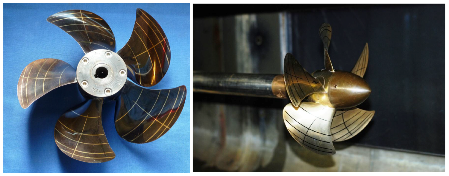
Potsdam Propeller CFD Benchmark Description
The high demand for improving the accuracy, quality, and credibility of the CFD simulation results, should be assessed by providing a high qualitative and intensive comparison with experimental measurement data.
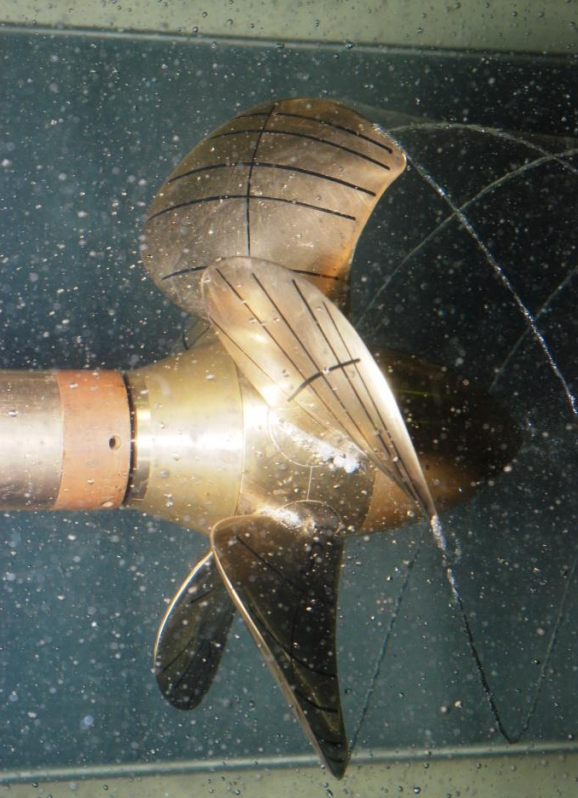
The purpose of this benchmark is the validation of CFD simulation software TCFD with the mesh created in high-end meshing software POINTWISE and to compare the results with the measurement data available. Potsdam Propeller Test Case (PPTC) is a marine propulsor that was extensively measured by SVA Potsdam and related data were published in [1], [2], and [3].
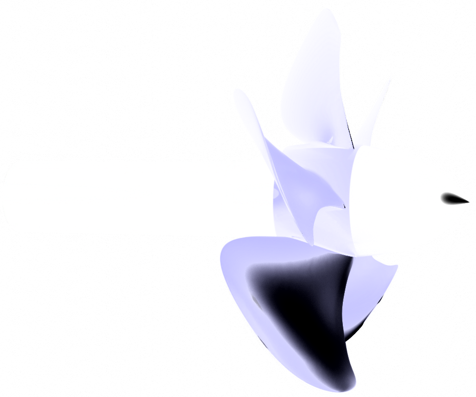
The particular goal of this benchmark is to compare the propeller Efficiency, Torque Coefficient, and Thrust Coefficient vs. Advance Coefficient with the real experimental measurement of SVA Potsdam Laboratory. The experimental investigation includes open water test and velocity field measurements at different operation conditions. A detailed description of the open water tests conducted at the towing tank of the SVA is presented in the SVA report [1], which can be found on the SVA website (sva-potsdam.de).
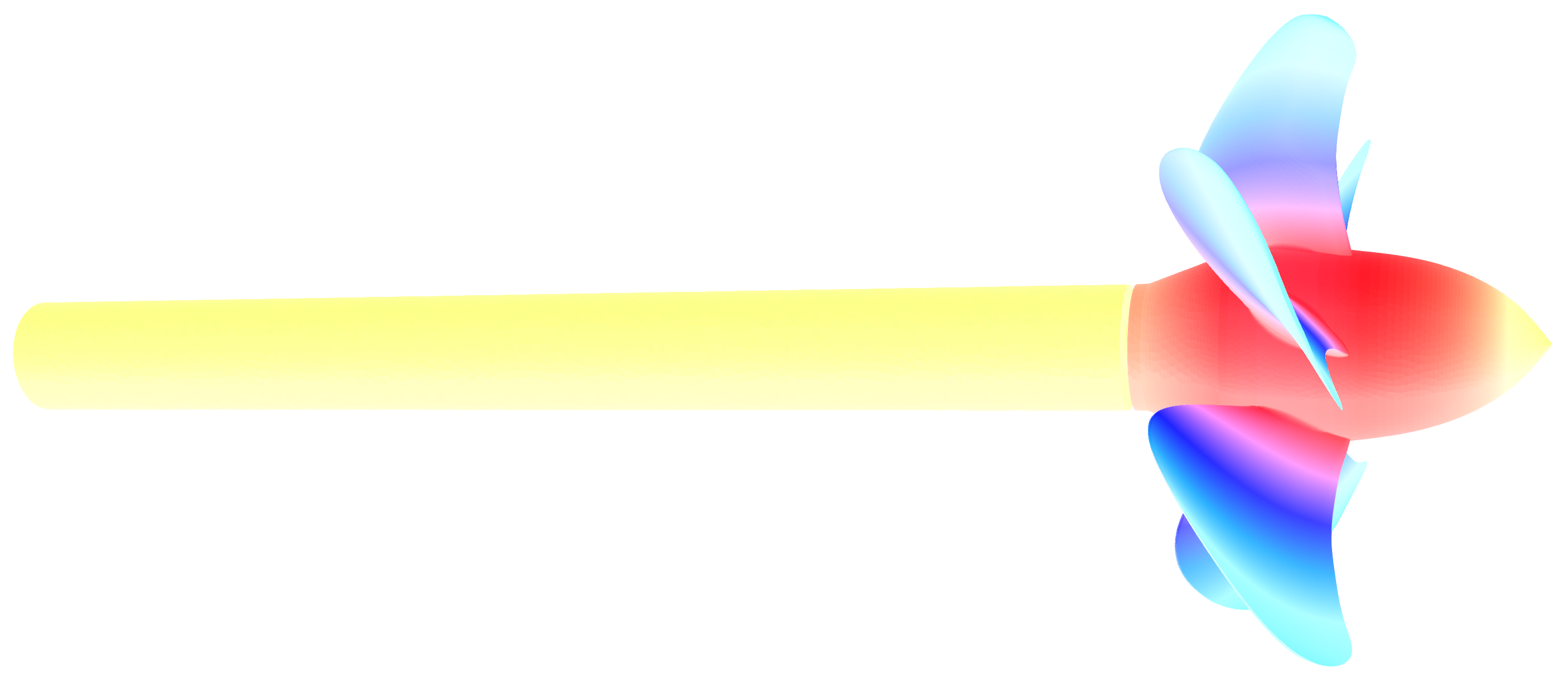
At the propeller analysis, there are a few important dimensionless numbers. Those are Advance Coefficient, Thrust Coefficient, Torque Coefficient, and Efficiency. They are defined as (respectively): J = Va/(n · D), KT = T/(ρ·n^2·D^4), KQ = Q/(ρ·n^2·D^5), η0 = J·KT/( 2π · KQ) Where Va is the advance speed [m/s], n is the speed of rotation [1/s], D is propeller diameter [m], T is thrust [N], ϱ is water density [kg/m3], Q is torque [Nm]. The measurement results are available for Advance coefficients from J = 0.5 to 1.6 and the simulation points are chosen accordingly. Altogether, 11 Advance Coefficient modes were simulated according to the measurements.
Potsdam Propeller Benchmark - POINTWISE Mesh
An unstructured viscous computational mesh was constructed with Pointwise on the Potsdam propeller geometry as part of this TCFD validation benchmark. Pointwise, Inc. has previously worked with variants of the geometry for other studies. For an in-depth discussion of Pointwise technology and how it can be used for this particular geometry, please consult [4]. A combination of anisotropic and isotropic triangles were used in the surface mesh discretization. Areas of high curvature – such as the leading edge, trailing edge, and the tipwere resolved by utilizing Pointwise’s T-Rex algorithm. This tool grows anisotropically stretched, right-angled triangles layered in the normal direction to a boundary [5], as shown below. Using this, areas of high curvature are able to be resolved without the need to isotropically refine the area. The result is an accurate adherence to the surface and a reduction in the point count. The interior of the surface mesh was resolved with isotropic triangles created using a modified Delaunay algorithm.
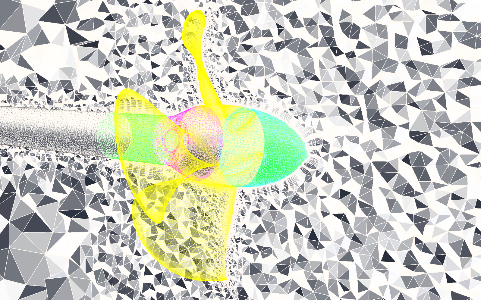
After meshing the geometry, the outer boundary of the moving reference frame (MRF) as well as the outer boundary of the computational domain were meshed utilizing isotropic triangles and the Delaunay algorithm. The MRF is cylindrical domain approximately 4.8 D long (4.8x the propeller diameter) and 1.5 D in diameter. It starts just upstream of the propeller and extends downstream into the wake. A farfield block was generated outside of the MRF corresponding to 10 D and 2.6 D; these were the limits taken from the file provided. The volume mesh is a combination of a prismatic core surrounded by isotropic tetrahedral cells. The prismatic portions of the grid were initialized using T-Rex. Starting from the surface mesh, anisotropic tetrahedral cells were grown until reaching a desired stop criteria, colliding with another front, or violating quality criteria. If an element stops advancing this did not prevent adjacent elements from continuing. After the tetrahedral layers are grown, the cells are combined to form prisms (or hexagons if the surface mesh is made up of quadrilateral cells). This reduces the total cell count of the mesh without sacrificing quality. Once the near-wall viscous mesh was generated, the remainder of the volume was populated with isotropic tetrahedral cells. The total cell count was just below 4.1 million cells. The average maximum included angle was 101, and the maximum was 170. The average volume ratio was 1.8 with a maximum of 28.
TCFD Case Setup
Complete CFD simulation setup is done in TCFD GUI in ParaView. Propeller has two components which are connected via interface.
- Reference density: 997.71 kg/m3
- Dynamic viscosity: 9.559 × 10⁻⁴ Pa⋅s
- CPU Time: 30 core.hours/point
- Turbulence: RANS
- Turbulence model: kOmegaSST
- Simulation type: Propeller
- Time management: steady-state
- Number of components: 2
- Wall treatment: Wall functions
- Mean flow speed: 4 m/s
- Rotation speed: 900 RPM
- Flow model: incompressible
- Mesh size: 4.1 M cells
- Medium: water
- Speedlines: 1
- Simulation points: 11
- Fluid: Water
- Reference pressure: 1 atm
TCFD Simulation Domain

The simulation run in TCFD is quite straightforward. The external mesh, created in POINTWISE, is simply loaded and the simulation parameters are set. The simulation type is the propeller. Time management is steady-state. The fluid flow model is incompressible. The mesh has two components (the water tunnel and the cylinder with propeller inside) of total 4.1M cells. The inlet flow velocity defines the advance coefficient and the velocity varies from 1.7 to 5.9 m/s in 11 points. The outlet boundary condition is static pressure. For turbulence modeling, the RANS modeling approach has been used with the k-omega SST turbulence model with the wall functions. The fluid properties of water are selected. The density of 997.71 kg/m3. Dynamic viscosity of 9.559e-4 Pa.s.

The simulation was executed in the automated workflow in steady-state mode, for 11 different flow rates. TCFD is capable of writing the results down at any time during the simulation. The convergence of any quantity is monitored during the simulation. When any simulation point converges sufficiently enough, the simulation can move onto the next simulation point. Single one point simulation takes about 30 core*hours.

TCFD Postprocessing
TCFD includes a built-in post-processing module that automatically evaluates the required total quantities, such as propeller efficiency, thrust coefficient, torque coefficient, forces, force coefficients, flow rates, and much more. All these quantities are evaluated throughout the simulation run, and all the important data is summarized in tabled .csv files as well as in the HTML report, which can be updated anytime during the simulation for every run. Furthermore, visual postprocessing of the volume fields can be done with ParaView.


Graphical interface
All the case settings are set in a graphical intergace. The TCFD graphical interface is based on ParaView. Most of the users prefer to use a graphical interface for case setup and then decide for example to use the command line for cluster run. The workflow is very flexible and the command line vs GUI decision is always on the user.

The component graph
Any project simulated in TCFD has its component graph. The component graph shows how the components are organized – the model topology. What is the inlet, the outlet and how the components are connected via interfaces.

Running CFD Simulation
The simulation can be run on any number of parallel processors. Immediately after the simulation is started, the user can follow the progress of all the important quantities in a HTML report: forces acting on the building surface, flow rates, residuals, pressure and many others. These run-time functions give the user valuable information of the simulation convergence and also the availability to stop the simulation before its expected end.


TCFD includes a built-in post-processing module that automatically evaluates all the required quantities, such as efficiency, torque, forces, force coefficients, flow rates, pressure, velocity, and much more. All these quantities are evaluated throughout the simulation run, and all the important data is summarized in an HTML report, which can be updated anytime during the simulation, for every run. All the simulation data are also saved in tabulated .csv files for further evaluation. Furthermore, visual postprocessing of the volume fields can be done with ParaView. ParaView is a very powerful open-source CFD postprocessing tool, and includes a large variety of useful visualization possibilities, as well as data operation possibilities.

Results #1 - Main Propeller Characteristics - POINTWISE Mesh
A very important result of hydro propeller simulation is propeller torque, which is a result of fluid flow pressure and viscous forces acting on the impeller surface. The resulting propeller power is calculated from a simple formula P = T · ω Where P is power [W], T is torque [N.m], and ω is angular velocity [rad/s]. The image on the right hand side shows the comparison of propeller power from CFD simulation compared to the propeller power gained from the experimental measurement. There were investigated 10 propeller modes (flow rates), corresponding to the 10 guide vanes openings.
Results #2 - Main Propeller Characteristics - snappyHexMesh
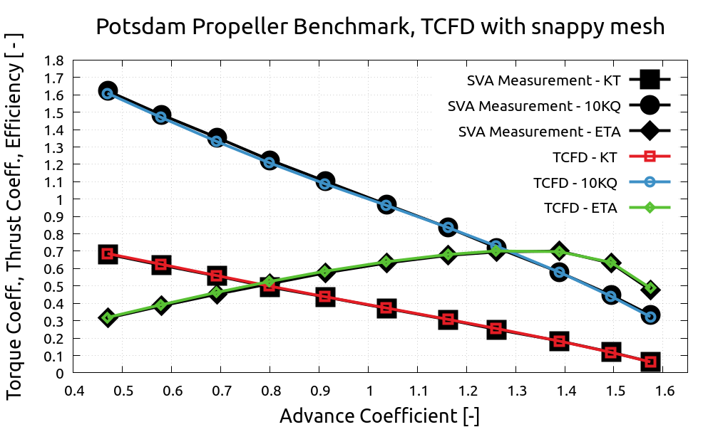
A very important result of hydro propeller simulation is propeller torque, which is a result of fluid flow pressure and viscous forces acting on the impeller surface. The resulting propeller power is calculated from a simple formula P = T · ω Where P is power [W], T is torque [N.m], and ω is angular velocity [rad/s]. The image on the right hand side shows the comparison of propeller power from CFD simulation compared to the propeller power gained from the experimental measurement. There were investigated 10 propeller modes (flow rates), corresponding to the 10 guide vanes openings.
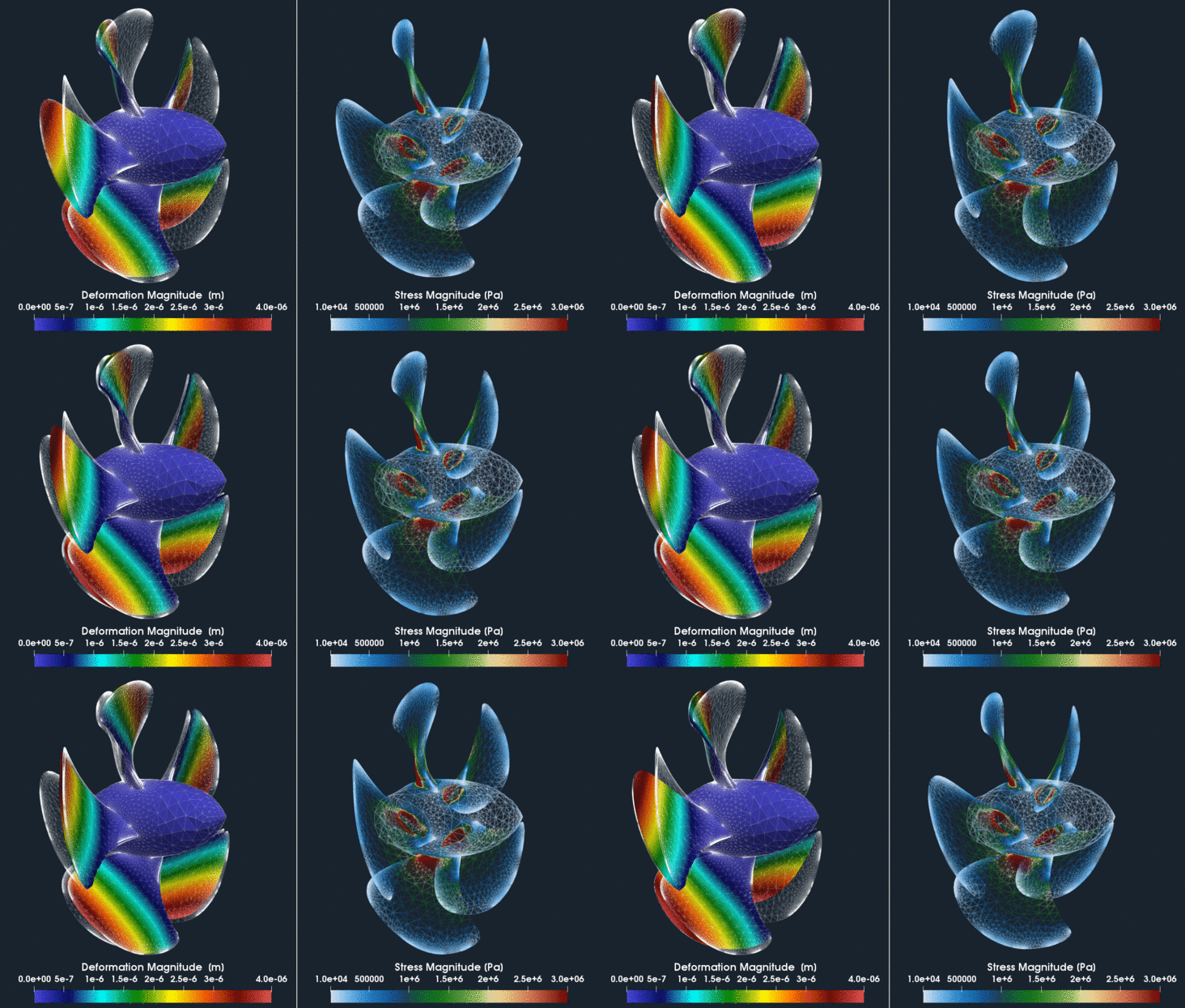
FEA Simulation - Deformation & Material Stress
Turbo Postprocessing - Meridional Average View
Another important hydro propeller simulation results evaluation is a visualization of a Meridional Average of simulated quantities. This visualization gives the user valuable information about how, for example, the total pressure is spent in the flow passage of the propeller. A special TCFD filter Meridional Average, created for ParaView, is applied and creates a geometrical slice (a plane), containing the rotation axis and the circumferential averages of all the field data projected onto this slice. The Meridional Average method ignores, for example, blades or other obstacles, and as a result the resulting averaging plane has a shape of a compact flow passage.

Turbo Postprocessing - Blade to Blade View
Another important hydro propeller simulation results evaluation is a blade-to-blade view. The blade-to-blade view offers a unique perspective for an inspection of the flow field properties between the blades, at a fixed relative distance between the hub and shroud boundary surfaces. In TCFD, blade-to-blade view can be generated in two steps: First, the cylindrical mesh of the rotating zone needs to be transformed (unwrapped) into a normalized rectangular block (1x1x2Pi). Second, the unwrapped block is to be cut at the prefered normal distance (0-1), between hub and shroud. A typically desired field view is, for example, streamtraces of the flow field or relative velocity at the impeller. The user can observe how smoothly the fluid flows and how effectively the fluid attacks the leading edges of the blades. The following images show a few slices between hub and shroud.

Conclusion
- The CFD analysis of the PPTC was performed successfully.
- It has been shown that the TCAE provides very accurate results that are in perfect agreement with the measurement data.
- TCAE showed to be a very effective tool for a comprehensive CFD simulation analysis of hydro propellers, at all stages of the design process.
- More information about TCAE can be found on TCFD website: https://www.cfdsupport.com/tcae.html
- Potential questions will be happily answered on request info@cfdsupport.com.
References
[1] TCFD Manual https://www.cfdsupport.com/download/TCFD-manual-v19.10.pdf
[2] TCFD Training https://www.cfdsupport.com/download/TCFD-Training-19.10.pdf
[3] Barkmann, U., Potsdam Propeller Test Case (PPTC) – Open Water Tests with the Model Propeller VP1304, Report 3752, SchiffbauVersuchsanstalt Potsdam, April 2011
[4] Barkmann, U., Heinke, H.-J., Potsdam Propeller Test Case (PPTC) Test Case Description, Second International Symposium on Marine Propulsors smp’11, Hamburg, Germany, June 2011, Workshop: Propeller performance
[5] Heinke, H.-J., Potsdam Propeller Test Case (PPTC), Cavitation Tests with the Model Propeller VP1304, Report 3753, SchiffbauVersuchsanstalt Potsdam, April 2011
[6] Carrigan, T., Bagheri, B., “A Study of the Influence of Meshing Strategies on CFD Simulation Efficiency,” NAFEMS World Congress 2017, NWC17-466, 2017.
[7] Steinbrenner, J. P. and Abelanet, J.P., “Anisotropic Tetrahedral Meshing Based on Surface Deformation Techniques,” AIAA-20060554, AIAA 45th Aerospace Sciences Meeting, Reno, NV.Wikipedia https://en.wikipedia.org/wiki/Potsdam_propeller
Download TCAE Tutorial - Potsdam Propeller Benchmark
File name: Potsdam-propeller-TCAE-Tutorial-21.09.zip
File size: 169 MB
Tutorial Features: CFD, FEA, FSI, TCAE, TMESH, TCFD, TFEA, SIMULATION, FDA PUMP, RADIAL PUMP, CENTRIFUGAL PUMP, TURBOMACHINERY, INCOMPRESSIBLE FLOW, DEFORMATION, DISPLACEMENT, STRESS, MODAL ANALYSIS, INCOMPRESSIBLE, RANS, BLOOD FLOW, STEADY-STATE, AUTOMATION, WORKFLOW, RADIAL FLOW, FULL IMPELLER, SNAPPYHEXMESH, NETGEN, 2 COMPONENTS, EXTERNAL MESH, POINTWISE, snappyHexMesh, 900 RPM
